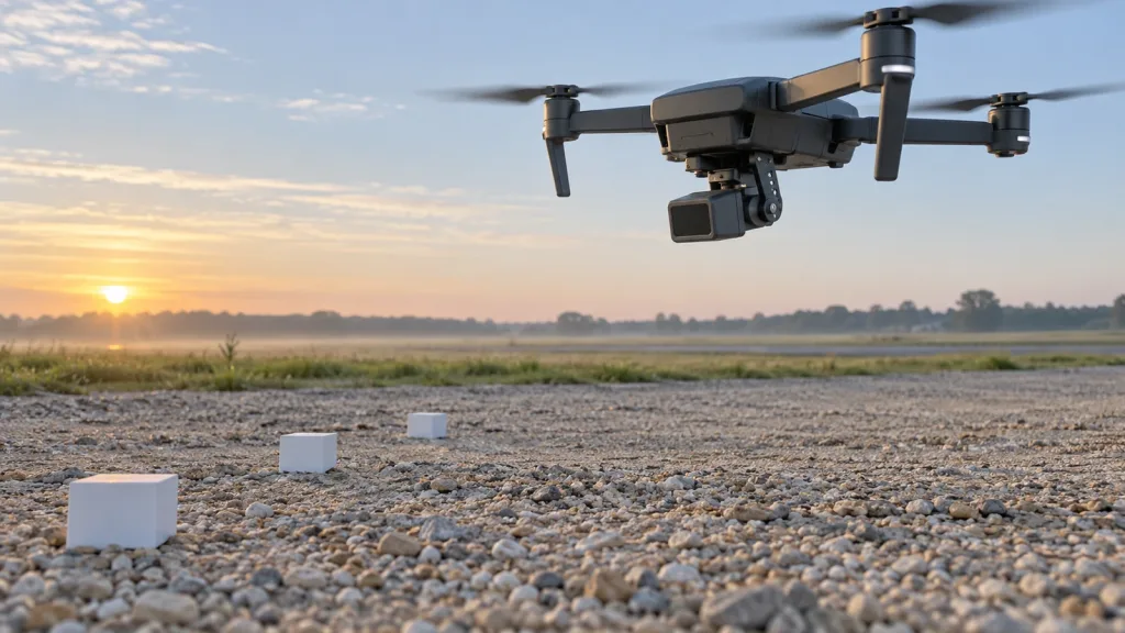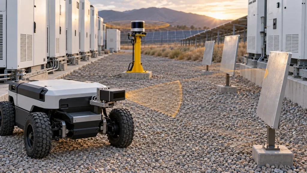
Drone LiDAR selection gets expensive when a UAV team jumps from a datasheet to a field trial without defining the inspection mission first. For utility-inspection programs, the real question is not whether a sensor can produce depth data in a demo, but whether it can give stable, actionable awareness around poles, insulators, fence lines, cabinets, and landing-zone clutter in bright outdoor conditions.
This guide is written for UAV integration engineers and technical buyers who need a practical screening workflow before they request samples, book a field pilot, or commit software time to a new perception path.
| Quick answer | Choose a compact drone LiDAR module only after you validate outdoor detection volume, update behavior, data path, mounting geometry, and a field-test acceptance sheet tied to your inspection mission. |
|---|---|
| Best fit | UAV teams building short-range inspection, obstacle awareness, altitude hold, or terrain-following workflows around substations, utility yards, and industrial assets. |
| Decision rule | If your team cannot define pass/fail thresholds for lighting, clearance margins, and logging workflow, the module is not ready for procurement. |
Why utility-inspection teams evaluate drone LiDAR differently
Inspection crews usually care about close-range structure awareness, controlled stand-off distance, and repeatable flight behavior near assets. That is a different problem from corridor mapping or a simple indoor range demo. STMicroelectronics positions Time-of-Flight sensing in robotics and drones for obstacle detection, cliff and collision avoidance, 3D mapping, and SLAM, which is useful market context. The engineering work starts after that: defining which objects matter, what clearance margin is acceptable, and how the aircraft should react when the depth signal becomes uncertain.
Flight rules also matter during evaluation. The FAA says operators must keep the drone within sight and avoid careless operations, while EASA guidance continues to emphasize continuous unaided visual contact in applicable operations. In practice, that means a perception module should support a safer workflow, not be treated as a substitute for operating discipline or contingency planning.
If your team needs the baseline primer first, Purpleriver already covers what drone LiDAR means for UAV integration teams. This article starts later in the buying cycle: qualifying a compact module for a concrete inspection mission.
Drone LiDAR decision matrix for inspection workflows
| Evaluation area | What to verify | Why it matters in inspection work | Reject if |
|---|---|---|---|
| Detection volume | FoV, minimum range, outdoor usable range, blind spots from airframe geometry | Inspection flights often approach angled structures and cluttered landing zones | The sensing cone misses asset edges or required clearance zones |
| Update behavior | Frame rate, latency, output stability, dropout pattern in bright scenes | The aircraft needs timely, believable data during approach and repositioning | No reliable control threshold can be defined |
| Environmental robustness | Ambient-light tolerance, reflective-surface behavior, vibration sensitivity | Utility yards mix metal, bright sky, cables, shadows, and dust | Performance falls below mission needs in daylight or reflective scenes |
| Output usefulness | Depth grid, point cloud, confidence handling, logging path | Data format decides whether your software team can integrate quickly | Outputs cannot be consumed or replayed by your bench stack |
| Program fit | Power, weight, interface, software support, documentation maturity | A good sensor still fails if it creates schedule risk for the UAV program | Bring-up depends on tooling your team does not have |
Exact featured-product parameters to validate
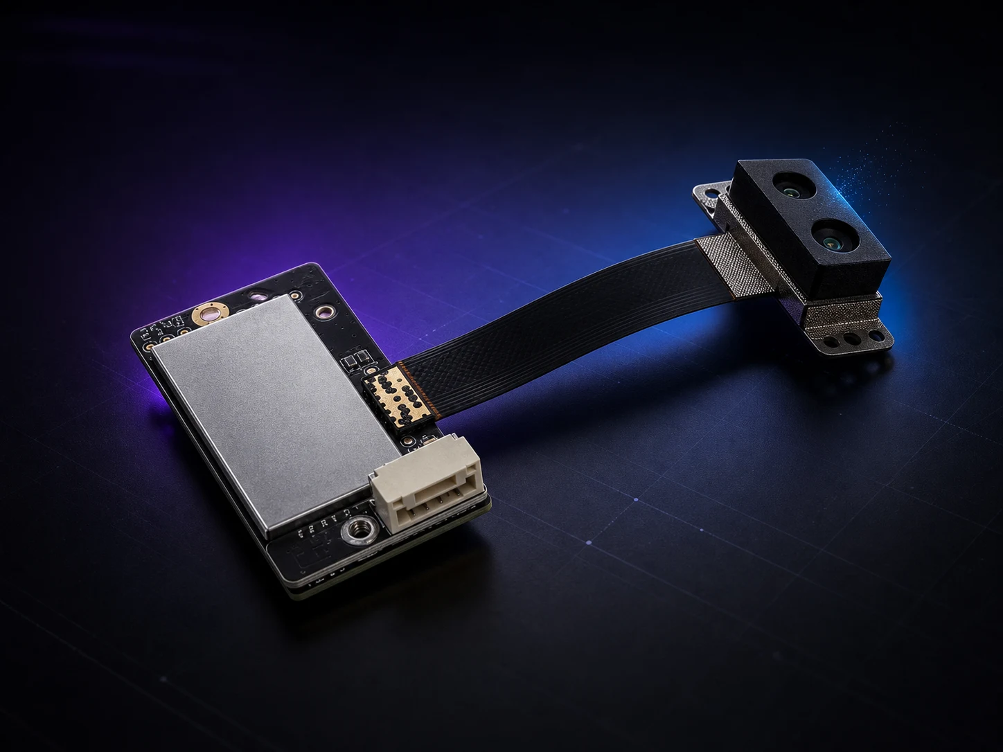
The current WooCommerce Featured product for this workflow is the LiDAR Drone Module – MRP-LD1 Solid-State dToF Sensor. Use these published facts as screening inputs, then confirm them against your own bench and field procedures.
| Parameter | Published value | Evaluation implication |
|---|---|---|
| Weight | 8g | Light enough for compact UAV payload budgets, but still verify cable strain relief and mount stiffness. |
| Power / supply | 1.2W at 5V | Check regulator margin and noise behavior during throttle changes. |
| Ranging principle | dTOF with SPAD scanning | Expect depth-oriented output and define how confidence is interpreted in software. |
| Emitter | 940nm VCSEL | Validate window material, glare conditions, and daytime test coverage. |
| Laser safety | Class 1 | Useful for screening, but still document the integration context and operating procedures. |
| Range | Indoor 0.5-25m; outdoor 0.2-8m | Use the outdoor figure for inspection acceptance, not the indoor headline range. |
| Ambient-light resistance | 80Klux | Run midday tests if your mission includes exposed substations or roof assets. |
| Accuracy | 0.2-1m <= +/-3cm; 1-5m <= +/-5cm; 5-8m <= +/-10cm; 8-15m <= +/-20cm | Translate each band into obstacle-clearance and hover-margin rules. |
| FoV | 60° x 45° | Model whether one sensor covers both forward approach and near-ground descent geometry. |
| Resolution / rate | 40 x 30 at 10fps | Enough for many near-field awareness tasks if your software can work with a compact grid. |
| Interfaces | UART / UVC / UDP | Pick the interface that minimizes logging friction during evaluation. |
| Software support | Windows / ARM / Linux / Android | Helpful when bench tooling and companion compute span multiple environments. |
Evaluation workflow from bench to guarded field trial
1. Define the inspection geometry before you power the module
List the structures the aircraft must perceive: fence lines, switch cabinets, insulator stacks, poles, railings, guy wires, or sloped ground near a landing zone. Then define approach speed, minimum clearance, manual takeover rules, and sensor mounting angle. A buyer who cannot write those constraints is still too early for a meaningful RFQ.
2. Start with the fastest logging path
The MRP-LD1 supports UART, UVC, and UDP. For evaluation, choose the path that makes capture and replay easiest rather than the interface you eventually expect to fly. Purpleriver’s documentation hub and sample datasets are relevant checkpoints because they help the team understand expected outputs before field scheduling begins.
3. Convert specs into a measurable acceptance sheet
NIST’s 2025 point-cloud evaluation work is a useful reminder that perception systems should be compared with quantifiable measurements. For a compact drone LiDAR module, the acceptance sheet should still include detection success by target type, dropout rate in bright scenes, frame-to-frame stability during vibration, and end-to-end latency into the control or alerting loop.
4. Model the sensing cone against the aircraft body
A 60° x 45° FoV can look generous on paper and still miss the exact surfaces that matter if the mount angle, landing gear, camera pod, or prop guards occlude useful regions. Before field work, draw the sensing cone against your expected pitch angles during inspection, approach, and descent.
5. Move to guarded outdoor tests with operational discipline
Field tests should confirm how the module behaves around metal edges, bright background contrast, and partial occlusion. The FAA and EASA references belong in planning because they reinforce the same principle: sensor evaluation should be wrapped in clear operating procedures, visual-contact discipline, and manual fallback behavior. That is especially important when the inspection team is close to critical infrastructure.
Interface, data, and integration planning
The schedule risk in a drone LiDAR program often sits between “the module outputs depth” and “the aircraft responds correctly.” Use this table to align perception, embedded, and flight-test owners early.
| Integration topic | Questions to answer |
|---|---|
| Mounting | Can the sensor keep a stable view without frame occlusion, cable movement, or prop-wash vibration? |
| Power path | Does the 5V rail remain stable during throttle transients and telemetry bursts? |
| Data product | Will your stack use a depth grid, a filtered point cloud, or a simpler obstacle metric? |
| Companion compute | Will parsing happen on Linux/ARM onboard, on a workstation during capture, or in both phases? |
| Latency budget | How long from sensor update to warning, hold, or avoidance action? |
| Replay workflow | Can the team review missed detections with synchronized flight data and video? |
For broader selection tradeoffs, see Purpleriver’s guide on how to choose a solid-state LiDAR module for drones. If your roadmap shifts from inspection awareness toward heavier mapping deliverables, the robotics 3D mapping solution page shows where data expectations start to expand.
Realistic application case: substation inspection with close-range structure awareness
Consider a quadcopter inspecting transformer aisles and switchyard structures. The aircraft does not need long-range terrain mapping. It needs dependable awareness of fence geometry, cabinet corners, posts, and changing ground slope while holding a controlled stand-off distance for image capture.
A realistic evaluation sequence is:
- Bench-test the module against representative targets at 1m, 3m, 5m, and 8m.
- Replay the data to see whether the output remains stable enough for the aircraft’s approach speed.
- Mount the module at a forward-down angle that covers both obstacle approach and landing-zone slope.
- Run guarded daylight tests around metal and high-contrast backgrounds.
- Define a fallback mode for low-confidence or dropped frames before any semi-automated behavior is enabled.
This kind of workflow is concrete enough for procurement and avoids the common mistake of evaluating an inspection sensor as if it were only an indoor demo device.
Common mistakes when screening drone LiDAR for inspection programs
- Using indoor range claims instead of the published outdoor range band for acceptance criteria.
- Ignoring how airframe pitch and landing gear cut into the useful sensing region.
- Testing only on soft indoor targets and never reproducing bright daylight reflections.
- Choosing the final interface architecture before choosing the fastest path for logging and replay.
- Treating depth output as automatically actionable without confidence thresholds and fallback logic.
- Assuming the perception module reduces the need for clear operating procedures near critical assets.
RFQ and engineering evaluation checklist
| Checklist item | Why it belongs in the RFQ or sample request |
|---|---|
| Inspection asset type and target obstacles | Matches the sensor’s range and FoV assumptions to real geometry. |
| Aircraft payload, power, and compute limits | Prevents a sensor fit problem from appearing late in the program. |
| Preferred evaluation interface | Shortens time to first meaningful data capture. |
| Lighting conditions | Clarifies whether midday outdoor performance is the gating criterion. |
| Acceptance distances and clearance margins | Turns a demo into a measurable decision process. |
| Replay and SDK expectations | Keeps perception, embedded, and flight-test teams aligned. |
| Mounting envelope and window constraints | Avoids late surprises around occlusion and enclosure design. |
When a compact drone LiDAR module is worth the next test cycle
If your team already knows the inspection geometry, the clearance margin, and the logging workflow it needs, a compact solid-state module can move from bench validation to guarded outdoor testing quickly. If those answers are still vague, tighten the evaluation plan before requesting hardware.
Purpleriver’s featured MRP-LD1 dToF module is relevant for UAV obstacle awareness, altitude hold, terrain following, robotics navigation, and industrial inspection workflows. To discuss fit for your program, use the contact page and include your airframe class, preferred interface, and target clearance distances.