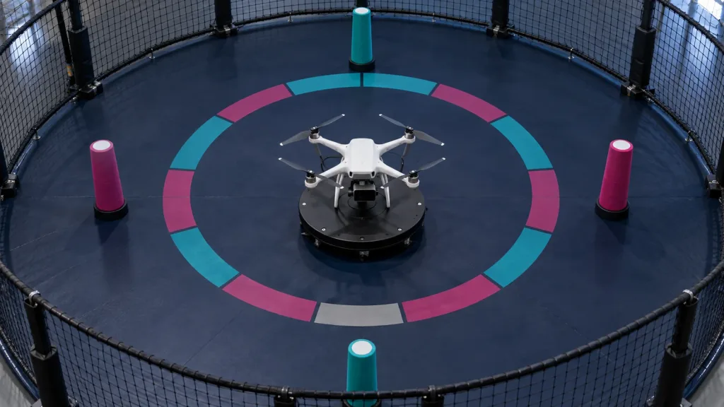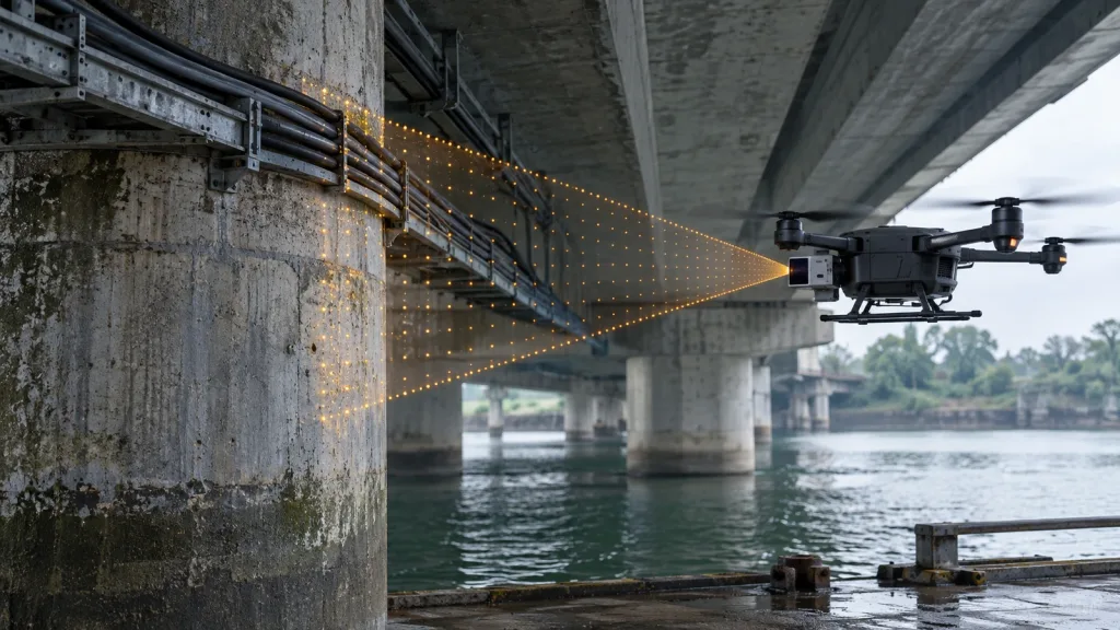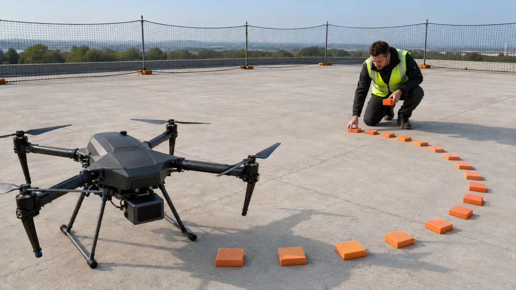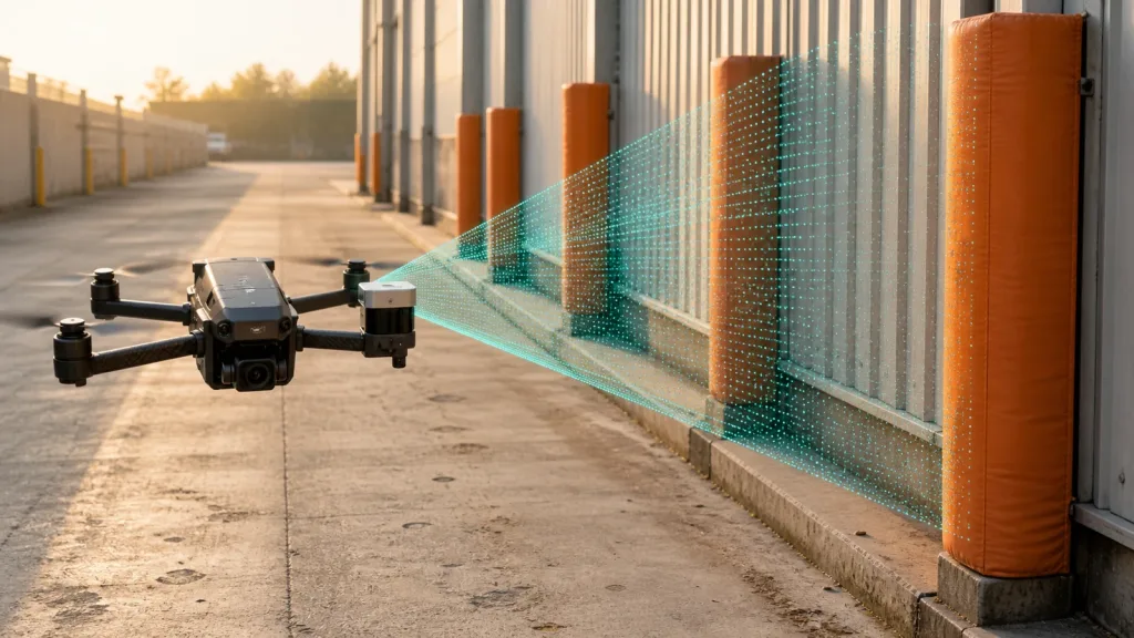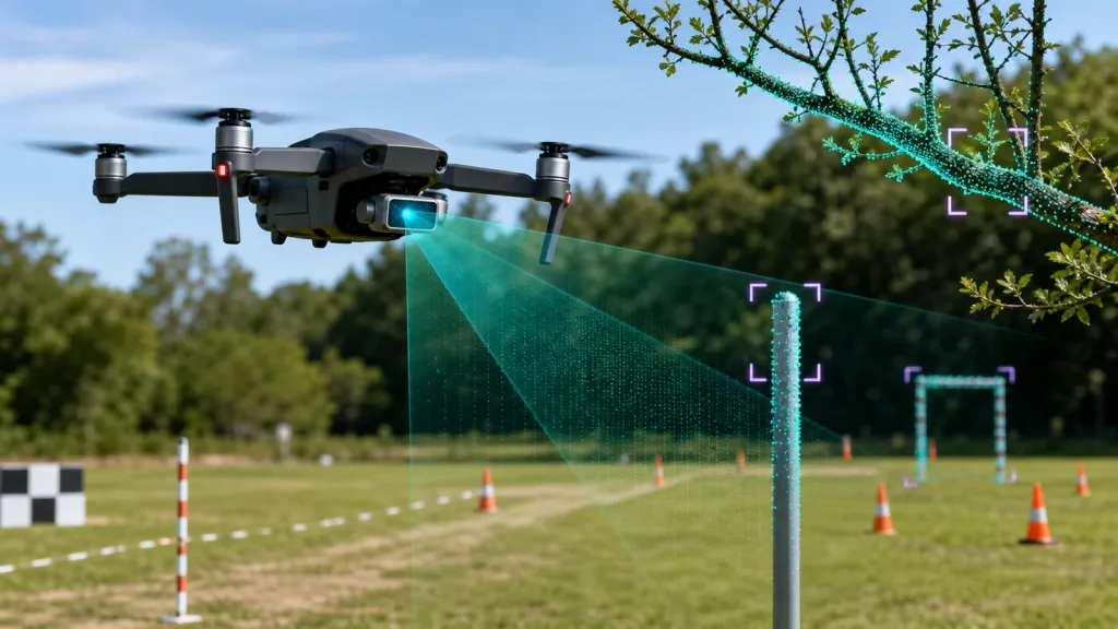
dToF LiDAR is most useful to a UAV team when it is evaluated as a full perception subsystem, not just as a range number on a datasheet. For drone obstacle avoidance and altitude hold, the real questions are whether the module gives enough field of view, enough confidence in strong ambient light, enough output structure for your stack, and a realistic path to flight-test validation.
This guide is written for integration engineers and technical buyers screening compact modules before they request samples or commit to a test plan.
| Quick answer | Choose a lightweight dToF module only after you verify FoV coverage, outdoor range, output format, mounting constraints, and the exact interfaces your autopilot or companion computer can use. |
|---|---|
| Best fit | Teams building low-altitude obstacle avoidance, altitude hold, terrain following, or short-range perception for compact UAVs. |
| Decision rule | If your test plan cannot define detection volume, confidence thresholds, and fallback behavior, the module is not ready for procurement. |
Why dToF LiDAR works for lightweight UAV obstacle-avoidance programs
A compact direct Time-of-Flight module can be easier to integrate than a heavier mechanical scanner when your aircraft is power-limited, payload-limited, and expected to react at short range. STMicroelectronics describes modern Time-of-Flight portfolios as compact, low-power systems used in robotics and drones, including obstacle detection, cliff and collision avoidance, 3D mapping, and SLAM. Hamamatsu’s SPAD materials are also useful context because they explain why single-photon avalanche diodes matter in low-light photon detection and LiDAR architectures.
That industry context does not remove the need for mission procedures. The FAA still requires operators to keep the aircraft within sight and avoid careless operations, and EASA guidance says operators should verify onboard detection equipment before flight and define procedures for potential conflict with other aircraft. In practice, that means your sensor evaluation should answer two different questions:
- Can this module detect the objects and terrain features the aircraft actually needs to react to?
- Can the aircraft still be operated safely when the sensor is degraded by glare, geometry, vibration, or workload?
If you need the broad system background first, Purpleriver already has a primer on what drone LiDAR means for UAV integration teams. This article starts one layer later: shortlisting and validating a module for a real project.
dToF LiDAR decision matrix for UAV teams
| Evaluation area | What to verify | Why it matters on a drone | Reject if |
|---|---|---|---|
| Detection volume | Horizontal and vertical FoV, minimum range, usable outdoor range | Too narrow and the aircraft misses wires, edges, or approach geometry | Coverage does not match flight envelope or landing profile |
| Update behavior | Frame rate, latency, confidence output, false positives | Reaction time collapses if the control loop runs faster than trustworthy updates arrive | No stable threshold can be defined for avoidance logic |
| Environmental robustness | Ambient light tolerance, vibration sensitivity, enclosure and window constraints | Outdoor drone use is where many lab-only sensors fail | Performance drops below mission needs in midday or reflective scenes |
| Output usefulness | Depth map, point cloud, confidence, reflectance, or simple range zones | Data format decides how much integration work moves into your stack | Output cannot be consumed by your flight computer or companion computer |
| Integration path | Power, weight, interface, SDK support, logging workflow | A good sensor still fails if it slows the rest of the UAV program | Bench bring-up requires custom tooling your team cannot support |
Exact featured-product parameters to validate first
Purpleriver’s current WooCommerce Featured product for this workflow is the LiDAR Drone Module – MRP-LD1 Solid-State dToF Sensor. If you are evaluating it for drone obstacle avoidance, treat these published product parameters as the baseline facts to confirm in your own test plan.
| Parameter | Published value | Evaluation implication |
|---|---|---|
| Weight | 8 g | Light enough for compact payload budgets, but still validate mount stiffness and cable strain relief. |
| Power / supply | 1.2 W at 5 V | Check regulator headroom and transient stability during takeoff and aggressive pitch changes. |
| Ranging principle | dTOF with SPAD scanning | Expect depth-oriented output and test confidence handling, not just nearest-object distance. |
| Emitter | 940 nm VCSEL | Verify enclosure window compatibility and field performance under strong ambient light. |
| Laser safety | Class 1 | Useful for product screening, but still document the integration context and operating procedures. |
| Range | Indoor 0.5-25 m; outdoor 0.2-8 m | Use outdoor figures for obstacle-avoidance acceptance, not indoor headline range. |
| Ambient light resistance | 80 Klux | Run noon or glare-heavy tests if your mission profile is daytime inspection. |
| Accuracy | 0.2-1 m <= +/-3 cm; 1-5 m <= +/-5 cm; 5-8 m <= +/-10 cm; 8-15 m <= +/-20 cm | Translate this into control margins and obstacle-clearance rules before flight. |
| FoV | 60° x 45° | Check whether one forward-facing module is enough or whether you need overlap from other sensors. |
| Resolution / rate | 40 x 30 at 10 fps | Adequate for many near-field tasks, but verify whether your autonomy stack wants denser spatial bins. |
| Interfaces | UART / UVC / UDP | Select the path that matches your logging and bring-up workflow, not just your final architecture. |
| Software support | Windows / ARM / Linux / Android | Useful if your bench tooling and companion computer span multiple environments. |
A practical dToF LiDAR evaluation workflow before procurement
1. Define the obstacle problem before you touch the module
List the obstacles that matter in your mission: tree branches, poles, fence lines, embankments, roof edges, powerline corridors, or landing-zone clutter. Then define approach speed, minimum stopping distance, avoidance maneuver, and the sensor mounting angle needed to see that geometry. This matters more than generic marketing phrases.
2. Map the detection volume against the aircraft envelope
A 60° x 45° FoV can be strong for forward perception on a compact aircraft, but only if you model what the prop guards, landing gear, gimbal structure, and pitch angle do to the usable field. For terrain following, the key question is often not maximum distance but where the bottom edge of the sensing cone intersects the ground during acceleration and descent.
3. Choose your integration path early
If your team wants the fastest bench start, the MRP-LD1 support for UART, UVC, and UDP is useful because you can separate early data capture from final flight-control integration. Start with the interface that makes logging easiest. After you know what the sensor outputs look like in motion, move toward the interface and processing chain you intend to fly.
Purpleriver’s documentation hub and sample datasets are relevant internal checkpoints here because they let a team inspect expected data structure and tooling before a field pilot is booked.
4. Bench-test with acceptance metrics, not impressions
NIST’s recent point-cloud evaluation work is a good reminder that perception systems should be compared with quantifiable measurements rather than subjective “looks good” review. For a drone module, your simplified acceptance sheet should still include:
- detection success rate at fixed distances and angles,
- confidence or stability across different target materials,
- dropout behavior under bright ambient light,
- repeatability with vibration and airflow,
- latency from capture to usable control input.
5. Move to guarded field tests with procedure support
FAA and EASA guidance makes the same operational point from different angles: sensing helps, but the operator still needs clear flight rules, trained observers when appropriate, and a documented response when the traffic or obstacle situation changes. For a UAV team, that means your field-test plan should document who watches airspace, what triggers manual takeover, and which sensor states disable automatic avoidance logic.
Interface, data, and integration checks
Most drone teams underestimate how much schedule risk sits between “the module outputs depth” and “the aircraft reacts correctly.” Use this section as the handoff between perception, embedded, and flight-test teams.
| Integration topic | Questions to answer |
|---|---|
| Mounting | Can the sensor keep a stable view without prop wash vibration or frame occlusion? |
| Power path | Does the 5 V rail stay clean during motor transients and telemetry bursts? |
| Data format | Are you consuming a raw depth grid, a filtered point cloud, or a simpler obstacle metric? |
| Companion compute | Will parsing and filtering happen on Linux/ARM, on a workstation during capture, or in a lighter embedded node? |
| Timing | What is the end-to-end latency from sensor update to avoidance or altitude command? |
| Logging | Can the team replay missed detections with synchronized flight data and video? |
For related design tradeoffs, Purpleriver’s article on how to choose a solid-state LiDAR module for drones is a useful companion read. If your roadmap extends beyond avoidance into mapping, the robotics 3D mapping solution page shows where the data requirements start to change.
Realistic application case: substation inspection drone needing near-field avoidance
Consider a compact quadcopter inspecting equipment aisles and approach paths around a substation yard. The aircraft does not need long-range corridor mapping; it needs dependable detection of posts, cabinet corners, fence geometry, and changing ground slope while remaining within a short stand-off distance.
In that case, a practical dToF workflow is:
- Bench-test the module on representative targets at 1 m, 3 m, 5 m, and 8 m.
- Replay the data to determine when the control system can still react smoothly at expected approach speed.
- Mount the module with a fixed forward-down angle to cover both obstacle approach and landing-zone terrain.
- Run guarded daylight tests to see how metal reflections and bright background contrast affect stability.
- Document a fallback mode when confidence drops below the project threshold.
That kind of test case fits well with Purpleriver’s stated UAV obstacle-avoidance application scope and avoids the common mistake of evaluating a drone sensor as if it were an indoor demo device.
Common mistakes when screening a dToF LiDAR module
- Comparing only maximum range instead of the usable outdoor range at the distances your control loop cares about.
- Ignoring field-of-view overlap with the aircraft body, payload, or pitch attitude.
- Testing indoors first and never building a midday ambient-light acceptance check.
- Choosing an interface based on final architecture and delaying the easiest path for logging and replay.
- Treating point-cloud or depth outputs as automatically actionable without confidence thresholds and fallback logic.
- Assuming the sensor replaces flight procedures even though operators still need airspace awareness and manual contingency plans.
RFQ and engineering evaluation checklist
| Checklist item | Why it belongs in the RFQ or sample request |
|---|---|
| Mission description and target obstacle set | Helps match range, FoV, and mounting assumptions to real use. |
| Aircraft payload, power, and processor constraints | Prevents a good sensor from failing a system-level fit check. |
| Preferred bench interface and logging format | Shortens time to first meaningful test. |
| Operating light conditions | Determines whether outdoor ambient resistance is the gating criterion. |
| Acceptance distances and response thresholds | Lets the team judge success before field work begins. |
| Data replay and SDK expectations | Keeps perception and flight-test teams aligned. |
| Mounting and enclosure constraints | Surface windows, tilt angle, and occlusion are often discovered too late. |
When a compact dToF LiDAR module is the right next step
If your team already knows the obstacle geometry, the control margin, and the logging workflow you need, a lightweight solid-state module can move quickly from bench validation to guarded flight testing. If those answers are still vague, pause the procurement cycle and tighten the evaluation plan first.
Purpleriver’s featured MRP-LD1 dToF module is relevant for teams evaluating UAV obstacle avoidance, altitude hold, terrain following, robotics navigation, and short-range depth perception. To discuss fit with your own integration workflow, use the contact page and include your aircraft class, preferred interface, and target detection distances.