
Capture
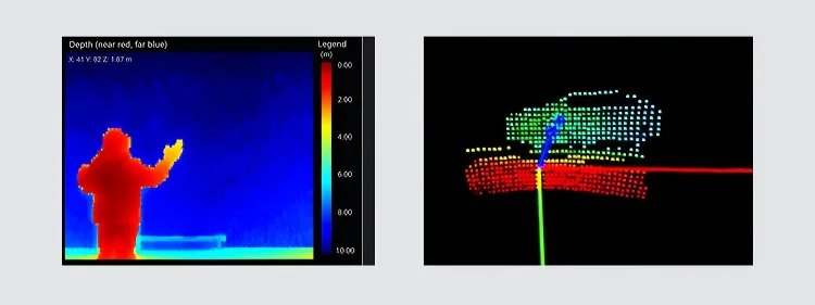
MRP-LD1 measures the configured scene and supplies 40 × 30 depth data and 3D point-cloud output.
Compact dToF depth and point-cloud input for robotics navigation, mapping and pilot-route evaluation.
Explore the moduleRobotics sensing solution
Evaluate MRP-LD1 as compact LiDAR for robotics navigation, mapping and obstacle awareness. The 8 g solid-state dToF module supplies depth and point-cloud input; the host robotics stack remains responsible for localization, planning and motion control.
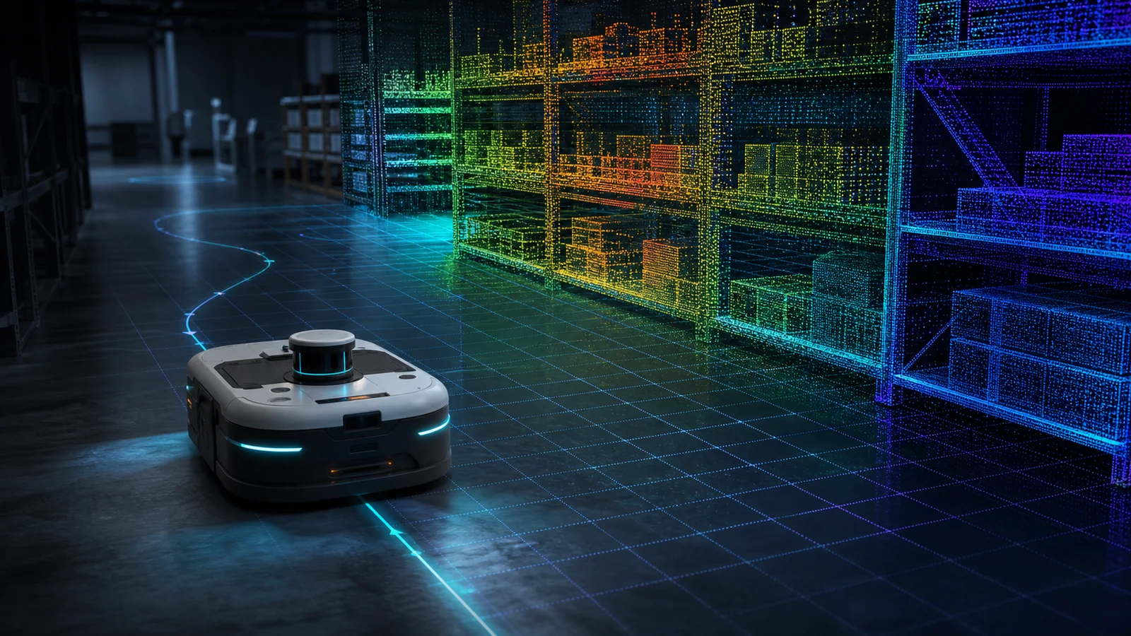
Robotics autonomy stack
A robotics mapping LiDAR module does not become an autonomous system by itself. Define the data contract and ownership at every step so the sensor, host software and robot controller can be tested independently.
MRP-LD1 measures the configured scene and supplies 40 × 30 depth data and 3D point-cloud output.
The host records units, axes, mounting pose and the transform from the sensor frame into the robot frame.
Robot software filters the measurements and uses them as input to mapping, obstacle awareness or navigation logic.
The robot controller retains velocity limits, stop behavior, fallback logic and final motion authority.
Task definition
Specify the object, route, response and data handoff before comparing range or resolution. The same module can be assessed differently for an aisle, dock, service-robot corridor or industrial zone.
Use robot navigation LiDAR data to evaluate aisle geometry, near-field objects and approach zones. Costmaps, route planning and stop commands remain host-side functions.
Review the module as a compact SLAM depth sensor input for corridors, lobby transitions and dock returns without presenting it as a complete SLAM package.
Evaluate object distance and scene geometry around workcells, restricted areas and docking locations with acceptance limits defined by the robotics team.
Connect documented UART, UVC or UDP paths to Windows, ARM, Linux or Android development environments for capture, replay and host-side testing.
MRP-LD1 module fit
MRP-LD1 uses SPAD direct time of flight with a 940 nm VCSEL and Class 1 classification. When evaluated as a robot obstacle avoidance dToF sensor, each listed value is a baseline for scene testing—not a guarantee that the host robot will detect or avoid every object.
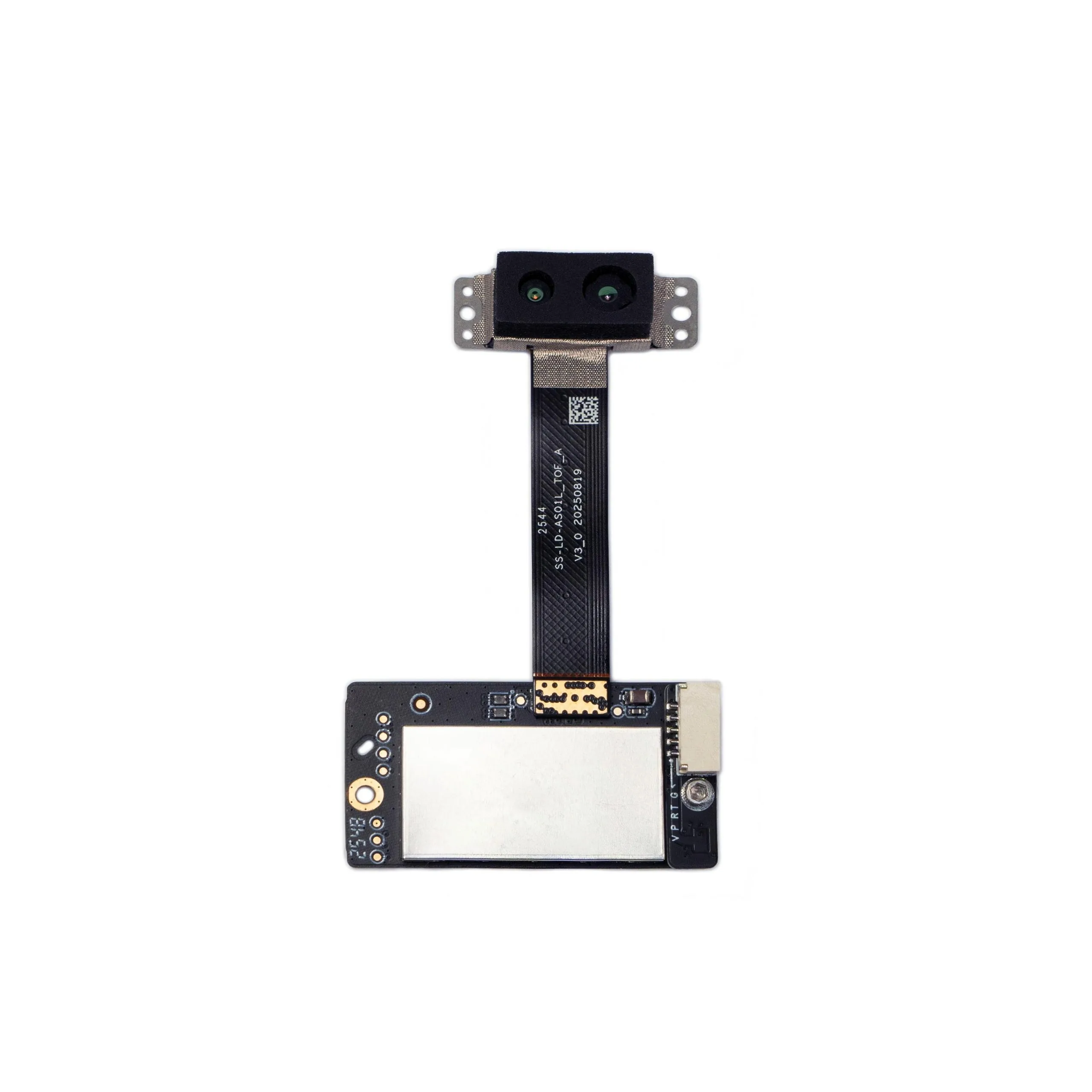
A documented baseline; validate the real target, background and route.
Keep indoor and outdoor evaluation limits separate.
Use mounting geometry to calculate floor and object coverage.
Measure the complete host and controller latency.
Review brackets, enclosure and cable routing as part of mounted mass.
Validate the actual rail and host power budget.
Test the real lighting direction, surfaces and enclosure.
Select the path that fits capture, bandwidth and replay needs.
Application scenes
Use representative layouts rather than one open-room demonstration. Route width, floor transitions, rack geometry, people, docks and target materials can all change the evidence available to the host perception stack.
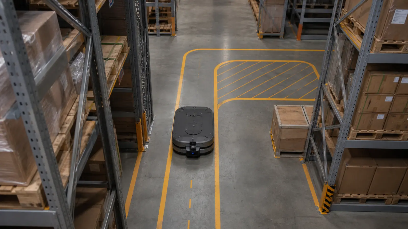
For an AGV AMR navigation LiDAR evaluation, record aisle width, rack overhangs, pallet edges, floor transitions, robot speed and the distance needed for a controlled response.
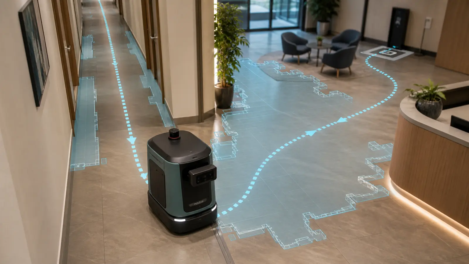
Test repetitive corridors, open lobby transitions, people moving through the field of view and the final approach to a dock. Preserve difficult sequences for replay.
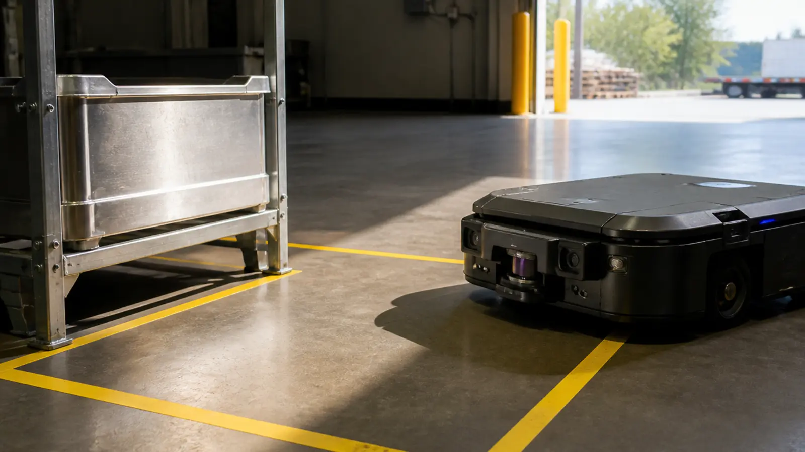
Evaluate bins, machine edges, restricted zones and low-contrast targets in the installed position. Define what the module measures and what the wider safety system must provide.
Depth and point-cloud handoff
Depth images and point-cloud output are useful only when the receiving team understands units, axes, invalid values, timestamps and mounting pose. Capture known-distance targets first, then repeat the review with aisle corners, low objects, rack edges and docking transitions.
For mapping or navigation evaluation, log the sensor stream with robot pose and controller events. This makes it possible to replay a difficult frame, distinguish sensor behavior from host processing and define a measurable pass/fail condition.
Mounting and operating envelope
A specification sheet cannot determine the final sensing envelope. Installation geometry, target surfaces, motion and end-to-end latency must be measured on the real robot.
Calculate where the lower field-of-view boundary meets the floor, then verify the result on the mounted robot. Excessive downward pitch can shorten forward coverage.
Map the near-field blind area, bumper, mast, payload and enclosure edges. Add sectors only where the application requires them.
Test dark, angled, reflective and partially transparent targets under the real illumination instead of relying on one high-reflectivity wall.
Measure sensing, transfer, filtering, decision and controller delay. Set robot speed from the verified response distance and fallback behavior.
Pilot-route validation
Keep the test conditions, configuration and acceptance limits visible. A successful demonstration should be repeatable across the representative route, not dependent on one favorable target.
Confirm 5 V power, the selected interface, units, timestamps, invalid values and known-distance targets before the robot moves.
Repeat tests with the real aisle, floor, object materials, lighting, target angle and working distance.
Measure pose, vibration, enclosure effects, occlusion and end-to-end processing delay on the intended platform.
Run conservative speeds through straight aisles, turns, transitions and docking approaches while recording sensor and controller events.
Save dropouts and unstable frames, reproduce them off-robot, document the boundary and require evidence before widening the operating envelope.
Engineering resources
Use the product page for approved specifications, request documentation for the host path, and review scene-matched data before building route-level acceptance criteria.
Review the complete approved MRP-LD1 specification, product video and application details.
View product details › ResourceRequest the user manual, SDK package and documented integration material for host-side evaluation.
Open documentation › ResourceDescribe the robot scene and request matched sample data before committing to a pilot route.
Request sample data › ResourceReview product, data, interface and purchasing questions before starting the evaluation.
Read technical FAQ ›Related engineering guides
Set mounting height and pitch with a floor-intercept test before route validation.
Read guide ›Define sensor axes, transforms, point-cloud fields and host ownership before integration.
Read guide ›Build measurable coverage, timing and failure-replay criteria for the installed system.
Read guide ›
Engineering and delivery support
Purpleriver develops compact solid-state dToF sensing modules for embedded UAV, robotics and depth-perception projects. Evaluation support can align the documented product, software environment, sample data and project constraints before a pilot build.
Robotics solution FAQ
Confirm the sensing boundary, mounting geometry, data handoff and acceptance criteria before requesting hardware.
Discuss your robotics projectNo. MRP-LD1 supplies depth images and 3D point-cloud data. Localization, SLAM, sensor fusion, costmaps, route planning, motion control and safe fallback behavior remain part of the host robotics system.
It can be evaluated as compact depth input for mapping, obstacle awareness and navigation workflows. Final suitability depends on the route, target geometry, mounting, host processing and acceptance criteria.
Use the documented 0.5–25 m indoor range as a starting baseline. Actual usable range depends on target size, reflectivity, angle, background, mounting and the response distance required by the robot.
That depends on the sensing task and object geometry. Evaluate whether the angular sampling, 60° × 45° field of view, 10 fps frame rate and host processing provide enough evidence for the intended route and response.
No. One module covers a documented 60° horizontal by 45° vertical sector. The integration team must plan mounting, overlap and remaining blind zones around the robot.
The documented software environments are Windows, ARM, Linux and Android, with UART, UVC and UDP interfaces. A ROS integration should be reviewed as host-side development against the available SDK and required message format; native ROS package support is not assumed.
Test the real material, size, angle, distance, background and lighting in the installed position. Record invalid or unstable frames and define the host response instead of assuming one universal detection result.
Share the robot type, sensing task, route, target materials, working distance, lighting, speed, mounting height and pitch, host platform, preferred interface, power limit, sample quantity and project timing.
Project-specific review
Share the robot, route, target, range, lighting, mounting, speed, host and preferred interface. Purpleriver can use those details to align the MRP-LD1 sample, documentation, data and next engineering discussion.
Drone LiDAR Quote
Share quantity, platform and integration needs. Justin Lu can follow up with quote, sample or technical support details.
Resource unlocked
Your inquiry has been submitted. You can download the requested resource now.
Download resource