Drones navigate and avoid obstacles through a chain of sensing, state estimation, path planning, decision logic and flight control. No compact sensor completes that chain alone. A sensor supplies evidence about the scene; the host combines it with vehicle state and mission rules; the flight controller executes a command; and the complete behavior must be validated on the actual aircraft.
Navigation and obstacle avoidance are related but different
Navigation answers where the drone is, where it should go and how to reach the goal. Obstacle avoidance addresses hazards that could invalidate the current path or require an immediate response. A navigation stack may use GNSS, inertial data, visual odometry, maps or other localization inputs. An avoidance stack adds nearby-scene sensing, risk assessment and a response that fits the aircraft’s dynamics.
The two functions share timing, coordinates and control authority. A locally safe avoidance move can conflict with a global route, geofence, return-to-home path or landing plan. That is why the system design must define ownership between perception, planning and the flight controller.
The five-layer drone navigation stack
- Perception: LiDAR, cameras, ultrasonic sensors, radar or other inputs describe nearby space and objects.
- Localization and state: the system estimates position, attitude, velocity and sensor frames.
- Planning: software selects or updates a route around constraints and mission goals.
- Decision: logic evaluates risk, confidence, priorities and degraded conditions.
- Control: the flight controller turns the decision into attitude, thrust and trajectory commands.
Validation must follow the same chain. A clean depth image does not prove a safe response, and a successful controller command does not prove that every relevant target was sensed.
How compact dToF LiDAR contributes
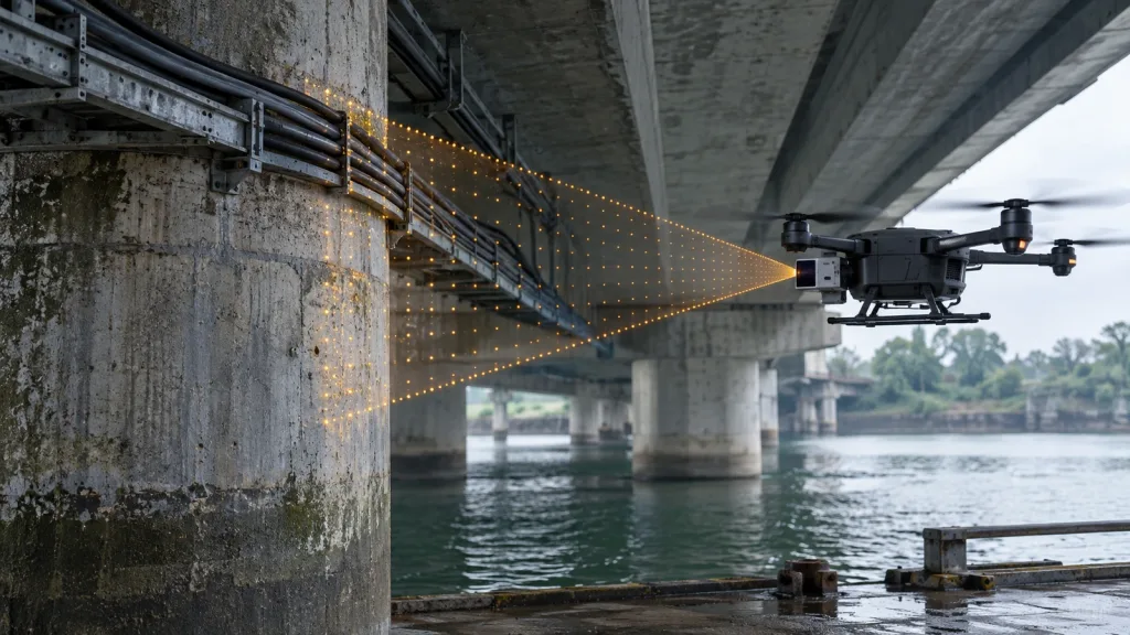
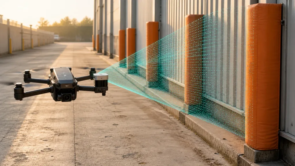
A dToF module emits light, detects returning photons and calculates distance from travel time. The resulting depth values can be organized as a depth image or used in a point-cloud workflow. The host can then filter invalid data, transform coordinates, identify occupied regions and provide inputs to higher-level logic.
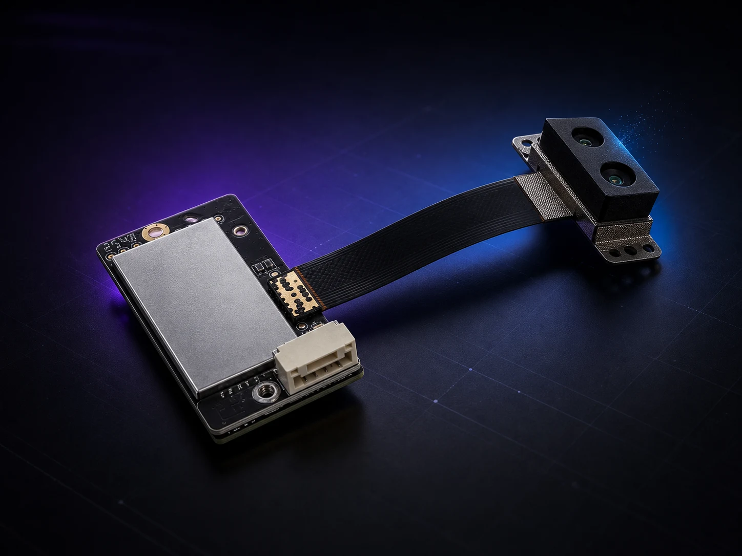
MRP-LD1 is a compact SPAD dToF LiDAR module using a 940nm VCSEL. Verified specifications include 8g weight, 1.2W typical power, 60° by 45° field of view, 40×30 output at 10fps, UART/UVC/UDP interfaces, and software support for Windows, ARM, Linux and Android. It lists 0.5–25m indoor range and 0.2–8m outdoor range with up to 80Klux ambient-light resistance.
These are component facts. The module does not perform SLAM, path planning or flight control by itself, and the separate indoor and outdoor ranges should never be merged into one range claim.
Plan forward, downward and rear-sector coverage
Forward sensing is often evaluated against closing speed and brake or turn margin. Downward sensing may support altitude input, terrain following or landing-zone review. Rear or lateral sensing may matter during reversing, orbiting or complex inspection routes. Each direction creates different occlusion, target and control questions.
Map the sensor field of view onto the airframe. Include the body, landing gear, propellers and enclosure. Check coverage as attitude changes, because a nominally forward sensor may point toward the ground or sky during acceleration and turns. If several sensors are used, verify overlap, coordinate frames and timestamp alignment.
Connect sensing distance to response margin
Avoidance margin is not the sensor range alone. It includes the distance available when a target becomes reliably detectable, plus sensor update time, host transport, filtering, decision latency, flight-controller response and vehicle dynamics. Higher speed consumes that margin faster. Narrow or low-reflectivity targets may also be detected later than a large flat target.
Measure each stage rather than assigning one guessed latency to the full chain. Use the worst observed values and include a safety margin appropriate to the test. If the system cannot stop or divert within the verified distance, reduce speed, improve sensing coverage or redesign the response.
Validate sunlight, reflectivity and blind sectors
Outdoor testing should cover direct and indirect sunlight, different target materials, angles, backgrounds and distances. The MRP-LD1 outdoor baseline is 0.2–8m, and up to 80Klux ambient-light resistance is listed, but the real mission still needs representative evidence. Do not infer performance on wires, branches, glass, black fabric or reflective metal from a wall test.
Blind sectors come from field of view, airframe geometry and sensor placement. Plot them explicitly and decide whether mission planning, additional sensors or restricted motion will manage them. Record invalid points and timeouts as data, not as noise to hide in a visualization.
Bench-to-flight test sequence
| Stage | Primary question | Evidence |
|---|---|---|
| Bench | Is the interface and data meaning correct? | Configuration, timestamps, units, invalid values and capture logs |
| Representative scene | Which targets and conditions are detected reliably? | Raw data, target notes, light, range, angle and repeat runs |
| Mounted | How do airframe and compute affect the result? | FOV map, occlusion, vibration, power and latency |
| Restrained flight | Does the handoff trigger the intended response? | Sensor-to-control timeline and abort behavior |
| Envelope expansion | Where are the verified limits? | Pass/fail matrix, misses, false responses and failure replay |