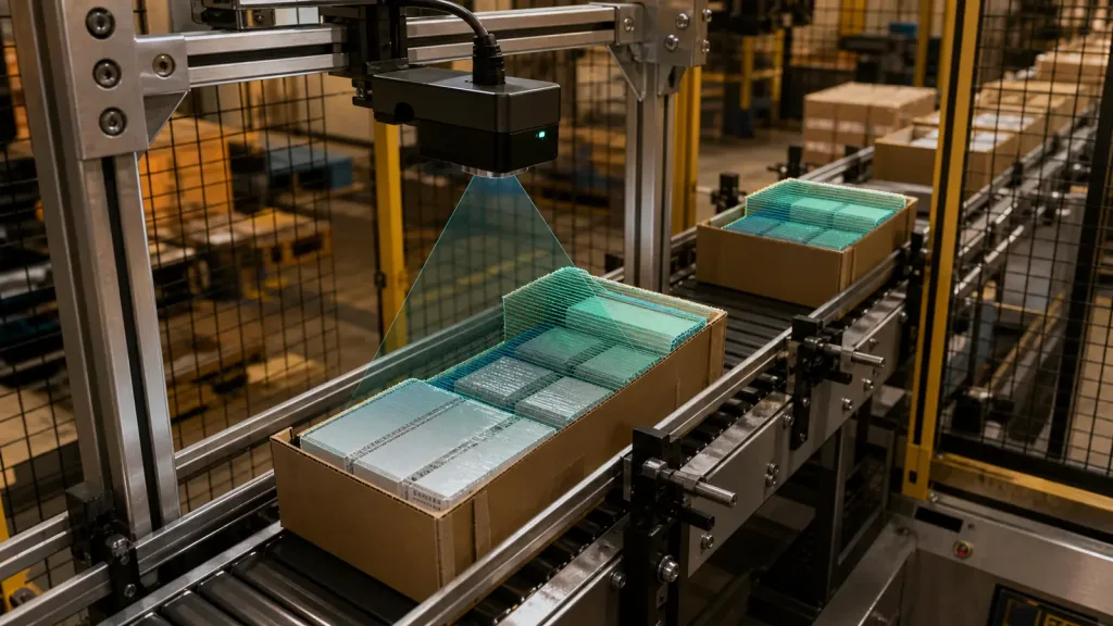
dToF LiDAR module decisions go wrong in factory projects when a team buys on range headlines alone and waits until installation week to discover blind zones, awkward host interfaces, or missing acceptance tests. In a short-range conveyor or inline inspection cell, the better question is whether the module can cover the actual detection volume, survive the lighting conditions, and produce replayable evidence before procurement moves forward.
This guide is written for automation engineers, machine-vision integrators, and technical buyers who need a practical way to screen a compact depth sensor before approving a sample or scaling an evaluation.
| Quick answer | Approve a compact dToF LiDAR module only after you map its field of view, working range, interface path, and validation evidence to the exact conveyor or inspection task you need to measure. |
|---|---|
| Best fit | Short-range industrial inspection cells checking presence, edge clearance, height variation, or protected-zone occupancy where compact size and low power matter. |
| Decision rule | If the team cannot define the detection zone, the lighting condition, and the pass/fail dataset it expects from the sample, the module is not ready for approval. |
Why a compact module can fit inspection cells
Compact direct Time-of-Flight sensors are attractive in inspection projects because they can add depth awareness without forcing a large mechanical payload, a spinning assembly, or a power-heavy subsystem into an already crowded station. STMicroelectronics describes direct ToF sensors as compact, low-power devices that integrate emitter, receiver, and processing in a small footprint, which aligns well with embedded automation tasks where installation space is limited. That category-level point is useful, but it does not answer the buyer question by itself.
The buyer still has to convert sensor facts into a cell-specific decision. A conveyor line does not care that a module works in a demo. It cares whether the sensor can see the carton edge, tray height, or zone intrusion that matters inside the real mounting envelope. Texas Instruments' Time-of-Flight system-design guidance is a good reminder that optics, acquisition flow, and system geometry matter together, not as isolated specification lines. That is why the right procurement workflow starts with the detection task and evidence plan, then works backward to the module choice.
If you need a broader site baseline first, Purpleriver already covers industrial inspection with compact dToF LiDAR modules. This article begins later in the buying cycle, when the team needs to decide whether a specific sample deserves budget and bench time.
dToF LiDAR module scorecard before sample approval
| Scorecard area | What to verify | Why it matters | Reject if |
|---|---|---|---|
| Detection volume | FoV, mounting height, minimum distance, edge coverage, occlusion from guards or brackets | The module is only useful if it sees the full carton, tray, or protected zone you actually need to measure | The usable cone misses the critical edge, gap, or height region |
| Mechanical and electrical fit | Weight, enclosure space, 5V supply quality, cable routing, vibration stability | Even small sensors fail when the station cannot mount or power them cleanly | The installation forces a redesign of the station frame or power path |
| Data usefulness | Depth output, replay workflow, frame rate, evidence capture, failure logging | The team needs repeatable evidence, not only a live demo | No one can replay the dataset or compare one test condition to another |
| Interface maturity | UART, UVC, or UDP suitability; host support; documentation path | The fastest proof path usually determines how quickly the team can approve or reject a sample | The evaluation depends on undocumented tooling or fragile packet handling |
| Environment risk | Ambient light, reflective wrapping, target color variation, conveyor motion blur, contamination near the window | Short-range inspection failures often appear in lighting and material edge cases first | The team cannot define a believable mixed-light or reflective-target test |
Exact featured-product parameters to screen
The current WooCommerce Featured product available for this workflow is the LiDAR Drone Module – MRP-LD1 Solid-State dToF Sensor. The module is broader than one drone use case: its published application scope also includes robot navigation, industrial inspection, and security. Use the listed facts below as screening inputs for a short-range cell, then confirm them through your own controlled tests.
| Parameter | Published value | Procurement implication |
|---|---|---|
| Weight | 8g | Helpful where the inspection head or bracket has limited payload margin. |
| Power / supply | 1.2W at 5V | Check whether the station power rail stays stable through I/O and actuator events. |
| Ranging principle | dTOF with SPAD scanning | Plan for depth-oriented validation rather than only 2D image review. |
| Emitter | 940nm VCSEL | Protective windows, glare, and bright ambient conditions belong in the test plan. |
| Laser safety | Class 1 (FDA Recognized Eye-Safe) | Useful for screening, but station-level guarding and procedures still matter. |
| Range | Indoor 0.5-25m; outdoor 0.2-8m | Inline cells usually care more about the close working band and repeatability than the headline maximum distance. |
| Ambient-light resistance | 80Klux | Run acceptance checks under skylights, open-bay light, or reflective packaging if those conditions exist on site. |
| Accuracy | 0.2-1m <= +/-3cm; 1-5m <= +/-5cm; 5-8m <= +/-10cm; 8-15m <= +/-20cm | Translate each band into carton-height tolerance, edge-clearance margin, or presence threshold. |
| FoV | 60° x 45° | Model whether one top mount sees the full inspection lane without dead zones near guides or side rails. |
| Resolution / rate | 40 x 30 at 10fps | Often sufficient for short-range presence and height checks if the workflow is designed around a compact depth grid. |
| Interfaces | UART / UVC / UDP | Choose the path that gets you the first replayable dataset fastest. |
| Software support | Windows / ARM / Linux / Android | Useful where bench logging and deployed control hardware differ. |
Evaluation workflow before procurement
1. Define the inspection task before the sample request
State the exact job first: presence check, edge-clearance check, height variation, zone occupancy, or reject confirmation. Then define the measurement window, line speed, mounting height, and failure condition. A buyer who starts with the datasheet instead of the station geometry usually gets a demo, not a decision.
2. Turn the module into a measurable approval sheet
NIST's standards roadmap for 3D imaging in robotic assembly is a strong reminder that time-of-flight systems should be judged with quantitative performance thinking. In a compact cell, that means the sample should be approved or rejected against written evidence such as miss counts, edge-stability behavior, replayable datasets, and repeatability across representative targets.
3. Choose the fastest proof path before the final architecture
The MRP-LD1 offers UART, UVC, and UDP. During evaluation, the best first interface is usually the one that shortens time to a replayable dataset, not necessarily the one the final PLC or embedded controller will use. Purpleriver's documentation hub and sample datasets are useful because they reduce early uncertainty before the team writes custom tooling.
4. Check mechanical and optical fit before fielding the cell
A compact module still needs a believable mechanical plan. Confirm whether side rails, brackets, cable exits, dust covers, or protective windows create partial occlusion. If the station includes glossy wrap, reflective metal, or strong side light, make those conditions part of the approval plan early. Purpleriver's articles on requesting an evaluation sample and diagnosing integration issues are useful complements here.
5. Freeze acceptance evidence before procurement expands
Once the team knows the inspection task and the logging path, write the approval sheet before asking for more hardware or integration effort. If no one can say what constitutes a pass, the program is still doing exploration, not procurement.
Interface, data, and integration planning
Compact depth sensors usually fail in projects because ownership is split: controls engineers think the sensor is solved once it streams, while application engineers still cannot prove that the data is usable. Use the table below to align the station design, the host path, and the evidence package early.
| Integration topic | Questions to answer before approval |
|---|---|
| Mounting geometry | Will the sensor keep a stable full view of the lane, or will guards, nozzles, rails, or brackets cut into the useful cone? |
| Power path | Can the 5V supply remain clean during actuator switching, lighting changes, or controller load spikes? |
| Output path | Is the team better served by UART, UVC, or UDP for the first round of logging and replay? |
| Host environment | Will evaluation live on Windows or Linux first, then move to ARM or embedded deployment later? |
| Data review | How will the team review failures: depth snapshots, exported logs, replay tools, or a lightweight dashboard? |
| Latency and action | What delay is acceptable between a detected height or clearance event and the station response? |
If the team needs more interface background before locking the proof path, review UART, UVC or UDP. If it needs broader deployment context, the product page and documentation set remain the best internal starting points.
Realistic application case: carton-height and edge-clearance checks on a conveyor cell
Consider a packaging line where cartons move under a guarded inspection head before they enter a diverter. The station wants two things from one compact depth sensor: confirm that each carton is present inside the lane and flag units whose top edge or side position drifts outside the acceptable envelope.
A practical evaluation plan for a compact dToF LiDAR module looks like this:
- Mount the module above the conveyor at the planned production height and map the 60° x 45° field of view against the full lane width.
- Capture repeatable datasets for empty belt, nominal cartons, low-height cartons, and edge-shifted cartons.
- Repeat the test under bright ambient spill and with reflective packaging materials if those conditions exist in the real cell.
- Validate that the chosen interface path lets the team replay misses and compare depth behavior across runs.
- Approve the module only if the evidence package shows stable detection in the true installation geometry, not only in a hand-held bench demo.
This is where a compact module can create value: not by replacing every inspection modality, but by giving the cell a clear depth-aware check in a footprint that is easier to integrate than a bulkier ranging system.
Common mistakes when screening compact depth modules for inspection
- Using the maximum indoor range as the main buying argument when the real task is a short, tightly bounded working volume.
- Ignoring guard rails, brackets, cable exits, or covers that clip the useful field of view after installation.
- Choosing the final deployment interface too early instead of the fastest proof path for logging and replay.
- Skipping reflective-material or mixed-light tests because the module looked clean in a controlled bench setup.
- Approving a sample without a written miss-rate, repeatability, and evidence requirement.
- Treating a compact dToF LiDAR module as a generic technology purchase instead of a station-specific measurement decision.
RFQ and engineering approval checklist
| Checklist item | Why it belongs in the RFQ or approval sheet |
|---|---|
| Exact inspection task | Keeps the conversation tied to presence, clearance, or height measurement instead of vague "3D sensing." |
| Working distance and mounting height | Prevents a nominal spec from masking a field-of-view mismatch. |
| Lighting and material conditions | Forces the evaluation to include skylight spill, reflective wrap, and other real failure modes. |
| Preferred first interface | Reduces time to the first usable replay dataset. |
| Host environment and tooling | Ensures the sample fits the actual bench and controls workflow. |
| Acceptance evidence | Defines the logs, screenshots, and repeatability checks required for approval. |
| Mechanical constraints | Surfaces rail, bracket, cover, and cable-routing problems before procurement advances. |
| Technical follow-up path | Lets the buyer move from evaluation to a focused vendor conversation through Purpleriver's contact channel. |
When a compact dToF LiDAR module deserves the next evaluation cycle
If your team already knows the detection zone, the real lighting condition, the logging path, and the evidence it needs to approve a sample, a compact module can move from shortlist to a meaningful inspection-cell trial quickly. If those answers are still vague, tighten the approval sheet before ordering hardware.
- Share the exact conveyor geometry, target type, and acceptance threshold instead of a generic inspection label.
- State the preferred interface and host environment so the evaluation starts with a usable data path.
Purpleriver, founded in 2015, develops solid-state dToF LiDAR technology and offers the MRP-LD1 module for applications that include industrial inspection. If your team has already built the scorecard, use it to start a technical conversation instead of a generic sample inquiry.
Contact Purpleriver with your inspection-cell scorecard so the next discussion starts from actual engineering constraints.