For UAV systems engineers and technical buyers: turn a sensor inquiry into a controlled evidence plan before you call a compact module an obstacle-avoidance solution.
A UAV obstacle avoidance sensor can provide useful range or depth evidence, but it does not by itself establish where an aircraft is covered, how observations reach a controller, or what the aircraft does when data are late or missing. The practical procurement question is therefore not “does the sensor detect an object?” It is “can our team document a direction-by-direction path from observation to a verified vehicle response?”
Quick answer
Choose and evaluate a UAV obstacle-avoidance sensor as one part of a coverage-to-control chain: define the directions that are sensed, the targets and conditions that matter, the timestamped data handoff, the controller’s response rule, and the response when data disappear. Treat a module’s stated range, field of view, output, and interface as screening inputs—not proof of all-direction coverage or flight-controller compatibility.
A UAV obstacle avoidance sensor is a data source, not an avoidance system
The integration boundary matters. A compact LiDAR may report depth images or point-cloud data, while a host process interprets that data, applies mounting geometry, identifies usable sectors, and sends an agreed representation to the flight stack. The flight controller or companion logic then applies a vehicle-specific response. Mounting, blind directions, update timing, controller tuning, propulsion response, and a loss-of-data policy remain aircraft-project work.
This distinction matches the concerns engineers raise when they ask about a flight controller plus sensor suite or navigation through narrow openings: they are asking about the chain, not merely a sensor label. Use those questions to prioritize your review, but validate the technical chain with documented interfaces and controlled evidence.
For example, PX4 documents collision prevention as a feature that can slow or stop a multicopter before an obstacle, but it also states that coverage, delay, tuning, and sensor range affect the result. It restricts movement where it has no sensor data unless a setting permits it. That is a useful reference model for an evaluation plan, not a claim that every compact sensor is a PX4-ready avoidance product. Read the current PX4 Collision Prevention guidance alongside your chosen flight stack’s documentation.
Start by placing the application in its real context. The UAV navigation and obstacle-avoidance solution context is a useful site-level starting point, but the project team still needs to name the aircraft, its operating direction, mounting location, host, controller, and test envelope.
Build a coverage-to-control contract before choosing hardware
Use this chart in a design review or supplier conversation. It prevents a common category error: judging a sensor from one forward-facing detection demonstration while the vehicle needs explicit behavior in several directions.
| Decision item | What to document | Evidence that closes the question |
|---|---|---|
| Flight direction and coverage | Forward, lateral, upward, downward, and rear directions that the operating concept requires; physical occlusions from arms, landing gear, payload, or enclosure. | A labeled airframe coverage drawing plus a bench capture for each intended sector. |
| Detection target and condition | Target material, shape, angle, distance band, ambient condition, relative motion, and whether the target enters from a sector edge. | Repeatable test notes and saved raw data for the conditions that matter to the mission. |
| Sensor-to-host handoff | Chosen physical interface, message/packet version, timestamp origin, frame convention, invalid-data representation, and responsible software owner. | A traceable sample capture and a decoder or adapter review—not an interface name alone. |
| Host-to-controller handoff | The project-owned conversion from sensor output into the controller’s accepted obstacle representation, including angular coverage and update behavior. | Controller-side log correlated to the source capture and an explicitly named mapping. |
| Vehicle response | The commanded response, clearance convention, delay budget, and the behavior when a sector is uncovered or data are stale. | A controlled, supervised response test with vehicle logs and an agreed pass/fail statement. |
Do not substitute a single “range” value for this table. A clearance decision depends on the whole response path: what the sensor observed, when the project software accepted it, when the controller acted, and how the particular aircraft responded. PX4’s documentation likewise treats sensor range, command tracking, acceleration, jerk, and configured delay as part of its collision-prevention behavior.
Screen the MRP-LD1 as an input to the contract—not as a complete aircraft claim
The current Featured-product record identifies the MRP-LD1 Drone LiDAR Sensor as a solid-state SPAD dToF module for evaluation. Its published data can help a team decide whether to request an evaluation sample and what to ask for next. It does not establish a native driver for a specific flight controller, a MAVLink bridge, full-airframe coverage, or a validated avoidance response.
| Published MRP-LD1 field | Exact published value | Question it helps screen |
|---|---|---|
| Ranging principle / scanning principle | dToF / SPAD | What sensing method and evidence format should the team evaluate? |
| Weight and power consumption | 8 g; 1.2 W | Can the project include these documented module values in its payload and power budget review? |
| Power supply | 5 V | What regulated supply and common-ground arrangement must the integrator document? |
| Listed range baseline | 0.5–25 m indoors; 0.2–8 m outdoors | Which project distances deserve controlled testing? Actual usable range still depends on the target, ambient light, angle, mounting, and motion. |
| Field of view and resolution | 60° (H) × 45° (V); 40 × 30 | What physical sector is covered by one mounting position, and which areas remain an airframe question? |
| Frame rate | 10 fps | What update behavior should be recorded in the application’s end-to-end timing review? |
| Output and interface | Depth images and 3D point-cloud data; UART, UVC, UDP | Which project-owned transport and conversion path will be tested? |
| Listed software support | Windows, ARM, Linux, Android | Which host environment can be evaluated? This is not a claim of flight-stack or ROS compatibility. |
For interface selection, compare the team’s acquisition and debugging needs with the site’s UART, UVC, or UDP interface guide. The right question is not which label sounds most capable; it is whether the selected path preserves enough evidence for your controller handoff and fault handling.
Document data semantics before connecting perception to control
A depth image or point cloud is not automatically an obstacle-control message. A project must decide how it maps points to the aircraft body, how it represents covered and uncovered sectors, how it handles invalid samples, and how it exposes age or timestamp information. That design belongs in the integration record.
For teams using MAVLink-based handoffs, the official OBSTACLE_DISTANCE message definition describes timestamped obstacle distances progressing across angles. It is a helpful checklist for discussing time, angles, sensor type, and coverage. It does not mean a LiDAR module emits that message without a project-specific adapter.
Also distinguish a narrow-ray range reading from a wider proximity arrangement. ArduPilot’s Proximity Sensors documentation explicitly separates typical narrow-ray rangefinders from wider-field proximity sensors and notes the need for configuration and exclusion zones. Use that distinction to ask where the aircraft frame blocks the view rather than assuming a field-of-view number describes the installed system.
If the application uses the MRP-LD1’s documented depth or point-cloud outputs, decide first which representation is needed downstream. The depth-map versus point-cloud guide can help frame that selection. Then save a short, versioned data contract covering source interface, frame, unit convention, timestamp policy, invalid-data flag, sector mapping, and software owner.
Why named conditions belong in the evidence pack
Do not turn a successful hallway capture into a universal performance promise. A 2025 SPAD dToF analysis examines how dead-time effects, photon flux, pulse width, and ToF quantization influence ranging precision. The useful project lesson is modest: label the conditions and timing of an evaluation so another engineer can understand what the evidence did—and did not—show. See Wu et al.’s SPAD dToF performance analysis for the underlying research.
Evaluation case: a supervised indoor-aisle response review
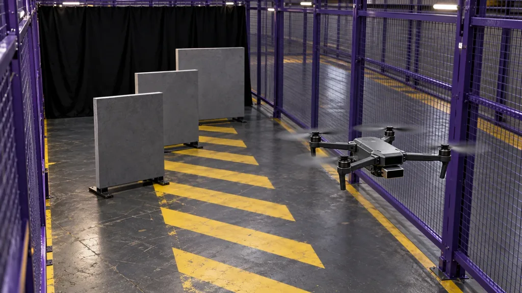
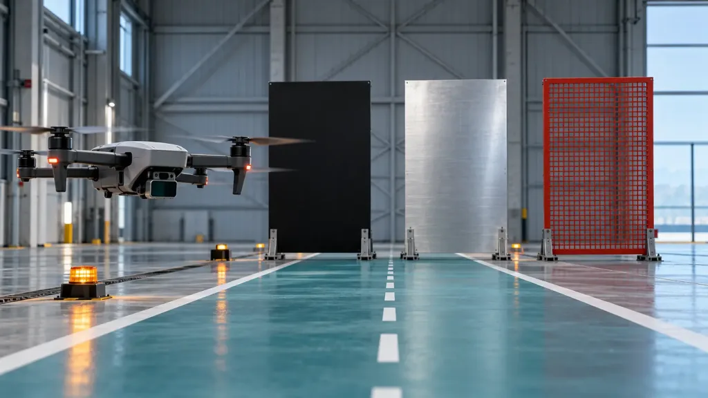
Consider a hypothetical multicopter evaluation in a marked indoor aisle mock-up. The team mounts a compact depth sensor in the intended forward position and defines a limited test envelope. A matte target, a metal-faced target, and an open mesh target are placed one at a time at controlled locations. The purpose is not to prove autonomous operation. It is to establish whether the team’s documented coverage-to-control contract can be observed end to end.
- Bench first: photograph the installed sensor, airframe obstructions, target positions, cable routing, and the intended forward body direction. Capture source data through the selected interface.
- Trace the handoff: record the source timestamp, the adapter or host receipt, the controller-side obstacle representation, and any dropped or invalid data. Keep the software and configuration version with the capture.
- Check sector edges: repeat targets near the stated coverage boundary and near physical occlusions. Mark them as covered, uncovered, ambiguous, or excluded—never silently covered.
- Review response with safeguards: in a supervised, program-approved procedure, compare the commanded response and logs to the written rule. If data are absent or stale, record the intended safe-state behavior rather than improvising a flight claim.
- Close the record: name the test conditions, evidence file locations, reviewer, open risks, and the next required test. A failed or ambiguous sector is useful evidence; it is not a reason to relabel it as covered.
This case produces a decision artifact a buyer can use: not “the sensor works,” but “these directions, conditions, handoffs, and responses have evidence; these other cases remain open.” For a focused loss-of-data follow-up, use the site’s no-data response drill.
Common mistakes that weaken an obstacle-avoidance evaluation
- Calling a forward sensor “all-direction avoidance.” A module field of view is not an airframe coverage map. Name every required direction and every occlusion.
- Equating an interface with a controller integration. UART, UVC, and UDP describe ways to acquire data; they do not prove a flight-controller message path or a vehicle response.
- Testing only one easy target. Record material, angle, placement, ambient condition, and sector edge. Do not generalize a single observation.
- Ignoring data age and loss. If timing, timestamps, invalid samples, or no-data behavior are undocumented, the handoff is incomplete.
- Mixing module facts with system claims. Keep published product fields separate from claims about host software, controller support, coverage, or validated behavior.
- Using Reddit or a demo clip as technical proof. Community questions are valuable for finding concerns, but the flight-test record and authoritative documentation must support publishable technical conclusions.
RFQ and evaluation checklist
Send this concise checklist with a sample or technical-document request:
- Airframe type, payload location, intended sensor orientation, and every direction that needs coverage.
- Target types, working-distance band, indoor/outdoor condition, motion, and required response concept.
- Requested source output: depth image, point cloud, or another documented representation.
- Preferred MRP-LD1 interface—UART, UVC, or UDP—and the host platform that will ingest it.
- Requested current protocol, sample capture, SDK/documentation materials, and version information.
- Project owner for the sensor parser, frame/sector mapping, controller adapter, and loss-of-data policy.
- Evidence required for each sector: mounting photo, source capture, controller-side log, test condition, and review outcome.
- Explicit statement that the evaluation does not assume a complete obstacle-avoidance system until the aircraft-specific response path is documented and tested.
Turn your sensor inquiry into an evidence request
Share your aircraft type, mounting direction, target distances, environment, host platform, preferred interface, and planned evaluation stage. Purpleriver can help start a documented discussion around the Featured MRP-LD1 module, technical materials, sample data, or an evaluation sample—without treating the module alone as a completed avoidance system.