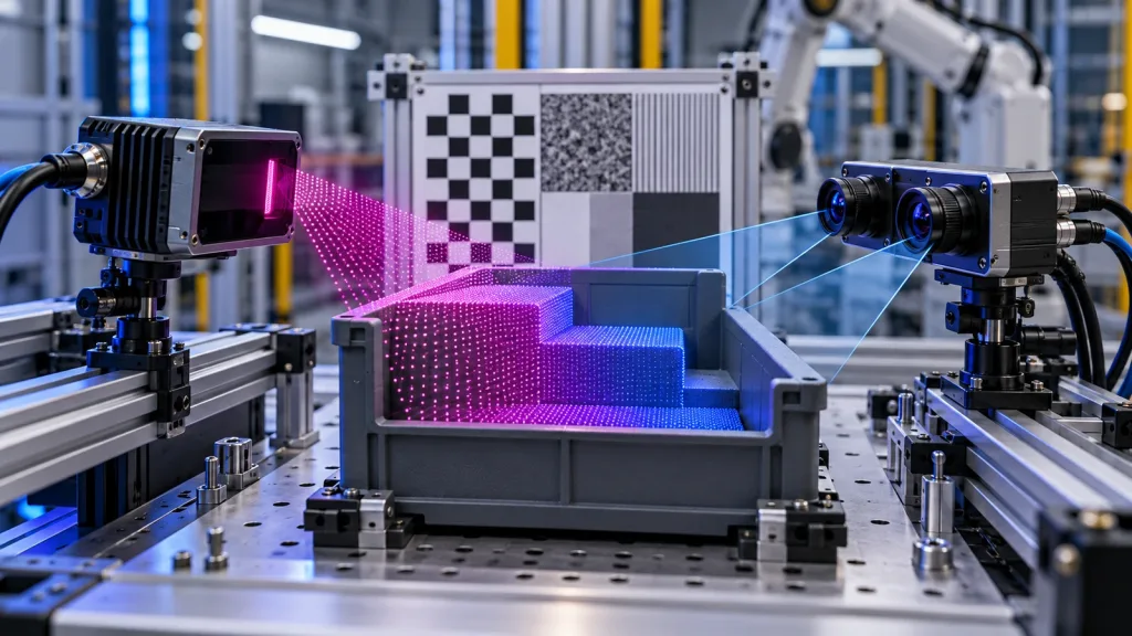
Machine Vision 3D dToF Camera: When to Add Depth Beside Stereo Vision
A machine-vision team evaluating a compact 3D sensor often asks the wrong first question: Which modality is better? The useful question is: which depth job must be proven at the fixture? A machine vision 3D dToF camera can be a focused depth layer for a known zone, while stereo can contribute richer scene imagery and disparity-based depth. Neither label proves that the needed tote edge, part, or clearance will survive the installed pipeline.
Quick answer
Evaluate dToF when the task calls for an explicit depth stream or point cloud in a defined field of view and the team can validate targets, lighting, mounting, and data age. Evaluate stereo when the application benefits from two synchronized images and can demonstrate reliable correspondence on the actual target surfaces. In many workcells, the disciplined choice is not replacement: use each modality for the measurement it can prove, then test the complete decision path.
1. Choose the depth job before selecting a machine vision 3D dToF camera
Start by naming the measurable event. It might be confirming that a tote is present in a fixed pickup zone, measuring the near face of a part before a robot enters, or generating a point set for a host-side check. Write the minimum target size, material, pose range, distance band, allowed miss behavior, acceptable data age, and the action that follows. This turns a modality debate into an acceptance question.
Stereo derives depth from corresponding locations in left and right images. OpenCV’s stereo-depth documentation expresses depth through disparity and describes texture thresholds, ambiguity filtering, speckle handling, and parameter tuning. That is a practical reason to capture representative low-texture, repeating, reflective, and occluded surfaces instead of accepting a clean demo image as proof.
Direct ToF is a different sensing architecture. ST’s current ToF overview describes compact direct-ToF systems that integrate emitter, receiver, and processing. Architecture alone is not a field result. A 2025 primary paper on SPAD-based dToF ranging precision also shows why photon flux, pulse width, quantization, and dead-time effects belong in an engineering discussion. Treat those sources as reasons to record conditions and test, not as a performance promise for a different module.
2. dToF or stereo? Use a decision chart, then collect evidence
| Question at the fixture | What to prove with a dToF depth layer | What to prove with stereo | Decision evidence |
|---|---|---|---|
| What is the depth output used for? | A depth image or point cloud creates an actionable zone measurement. | Disparity-based depth adds value beside the paired images. | Trace one target through acquisition, filtering, decision, and actuator handoff. |
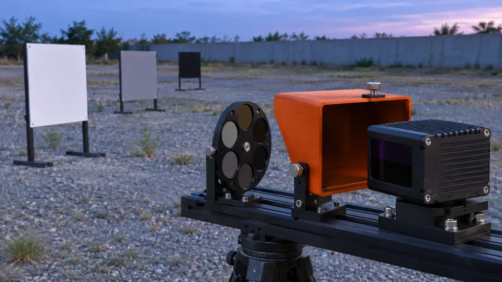
| Which surfaces matter? | Test reflectivity, angle, background light, and the installed window or mount. | Test texture, repeated patterns, exposure balance, occlusion, and calibration stability. | Use the same target matrix at the full pose and distance envelope. |
| How much scene coverage is needed? | Map the usable field and resolution to the target’s angular size. | Map baseline, lens view, disparity range, and image overlap to the task. | Save raw captures and mark the pixels or points that trigger the decision. |
| What happens when depth is uncertain? | Define invalid, out-of-range, stale, and no-data handling. | Define unmatched, low-confidence, occluded, and stale-frame handling. | Run interruption and difficult-surface tests before enabling automation. |
| Is one sensor required to do everything? | Do not assume it supplies object class, grasp pose, and safety logic. | Do not assume an image pair guarantees a usable depth measurement. | Assign each sensing output a bounded role in the perception stack. |
The table is deliberately not a scorecard. A feature list cannot answer whether a narrow dark lip is visible after the actual bracket, exposure choices, filters, and timing path are in place. If the system needs both an image-based task and a compact depth gate, a combined proof-of-concept may be more informative than a forced either/or choice.
3. Evaluate the published MRP-LD1 facts against the job
For teams considering a compact module, the MRP-LD1 Drone LiDAR Sensor listing is the product-fact source. Its values are inputs to an evaluation plan, not proof that a complete workcell will meet an outcome.
| Published MRP-LD1 parameter | Evaluation use |
|---|---|
| Solid-state SPAD dToF; 940 nm VCSEL | Record the sensing architecture in the test plan; do not infer performance from architecture alone. |
| 40 × 30 resolution; 10 fps | Place the smallest required target at representative poses and count useful depth evidence through the whole pipeline. |
| 60° horizontal × 45° vertical FOV | Draw the installed coverage, including bracket, cable, enclosure, and target-height effects. |
| Depth images and 3D point-cloud output | Decide which representation reaches the host and document units, axes, invalid values, and timestamps. |
| UART, UVC, and UDP; Windows, ARM, Linux, Android listed | Choose the actual host path and verify framing, bandwidth, restart behavior, and retained metadata. |
| 0.5–25 m indoors; 0.2–8 m outdoors; 80 Klux listed | Use these as a starting envelope only. Test the installed target, light, angle, motion, and contamination conditions. |
| 8 g; 1.2 W listed | Confirm mechanical, power, thermal, and cable constraints in the intended assembly. |
The listing identifies a module, not a complete obstacle-avoidance, inspection, or robot-safety system. Host processing, perception rules, motion logic, and validation remain project work. For a general comparison of data representations, see the site’s depth map versus point cloud guide.
4. Worked case: a tote lip that stereo cannot merely be assumed to solve
Illustrative engineering scenario—not a customer result: a robot loads inserts from a matte tote at a fixed station. The application needs a go/no-go depth condition before the robot enters a narrow zone. It also needs images for a separate vision task. The team must decide whether a compact dToF layer, stereo, or both deserves a prototype.
The team first builds a target matrix: empty tote, nominal insert, low dark insert, glossy protective film, offset insert, repeated rib texture, and partial occlusion. It sets the actual station distances and samples several approach positions. The acceptance rule is not “the image looks good.” It is whether the required target produces a traceable, timely, usable measurement at the point where the robot must decide.
For stereo, the team logs left/right frames, calibration version, exposure settings, disparity or confidence output, and why an unmatched region was rejected. For the dToF path, it logs raw depth or cloud, target pose, mount, light condition, invalid-value semantics, and data age at the host. Both paths are interrupted deliberately to ensure an old frame cannot masquerade as current evidence.
The result may be stereo for the visual task plus a dToF depth gate for the bounded zone, or a single approach that passes the matrix. The evidence—not a generic claim that one modality wins—sets the architecture.
5. Define the data and integration contract before tuning perception
Integration starts with what the host can trust. Before selecting filters or thresholds, record the sensor optical frame, the transform into the robot or fixture frame, acquisition versus reception versus publication timestamp, depth units, image row/column convention, point-field layout, confidence or invalid-value behavior, and version identifiers. A depth value without those terms is difficult to validate or reproduce.
For the MRP-LD1, choose the intended UART, UVC, or UDP route rather than treating interface names as an integration guarantee. The site’s UART, UVC, or UDP guide and compact dToF evaluation workflow can help frame the host-side questions. Confirm the current protocol, sample data, and available resources before writing conversion code; the documentation resources are the right starting point for that request.
A useful acceptance log holds a raw capture, transformed output, decision output, and configuration snapshot together. That makes a failure diagnosable: was the target not measured, filtered out, delayed, transformed incorrectly, or handled incorrectly by the downstream state machine?
6. Common machine-vision depth-selection mistakes
- Asking which modality is best in the abstract. Begin with the measurable event, target envelope, and failure behavior.
- Using a white calibration board as the only target. Include real surface texture, gloss, ribs, gaps, film, and occlusion.
- Treating nominal resolution as target detectability. Angular size, pose, range, valid pixels or points, and filtering all matter.
- Equating an interface with a complete software stack. Validate actual packets, metadata, driver scope, recovery, and host ownership.
- Ignoring stale data. A repeated old depth frame or disparity map must remain distinguishable from a current observation.
- Removing difficult points before saving evidence. Preserve raw captures so the team can distinguish sensing limits from post-processing effects.
- Calling a perception prototype a safety function. Keep sensing validation separate from the project’s risk process and safety architecture.
7. RFQ and evaluation-sample checklist
Send the supplier a bounded test question. A useful request includes:
- the target geometry, smallest feature, materials, pose envelope, working-distance band, and representative light conditions;
- the required decision, maximum accepted data age, invalid/no-data behavior, and what the host must do on uncertainty;
- the proposed mount, optical-center location, enclosure/window, cable routing, power, thermal, vibration, and contamination constraints;
- the needed depth image or point-cloud fields, coordinate convention, units, timestamps, confidence semantics, and sample captures;
- the intended UART, UVC, or UDP host path, operating system, bandwidth, packet-loss detection, startup, and recovery requirements;
- the current protocol, SDK, firmware, calibration, and version documentation needed to evaluate the module;
- the stereo camera baseline, calibration plan, image controls, disparity/confidence output, and target set if stereo is also being evaluated; and
- the acceptance matrix, raw-data retention, pass/fail evidence, and change-control questions for the proof-of-concept.
Turn the sensing question into an evaluation plan
Share the target size and surfaces, distance band, lighting, station geometry, host platform, desired data output, and the decision that follows. Purpleriver can help you compare those requirements with the published MRP-LD1 parameters and prepare questions for an evaluation sample.