UAV integration review
Calling a layout Omnidirectional Obstacle Sensing does not make the airframe all-around aware. A useful claim needs a coverage map: which direction is owned, what can block that view, which data path receives the observation, and what test record shows the hand-off worked. This guide gives a practical review sequence for teams evaluating a compact sensor layout for UAV navigation and obstacle avoidance.
Omnidirectional Obstacle Sensing is a vehicle-level evidence claim
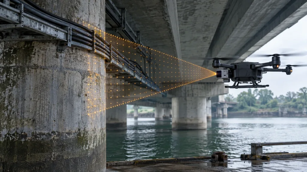
A module may see a useful directional volume; the aircraft-level question is different. The review should describe forward, side, rear, upper, lower, and transition regions in the airframe coordinate system. Then it should state which regions are intentionally out of scope. That keeps a product specification, an installation drawing, and a flight-control decision from being merged into one untested promise.
The FAA’s current Detect and Avoid Equipment and Systems checklist makes the same distinction for a safety case: it asks where sensors are located, the specific directions they face, the operational volume covered, limitations, and timing from detection through alert and avoidance. Its guidance explicitly notes that directional LiDAR, radar, and vision sensors have limited fields of view rather than omnidirectional coverage. Use that as a documentation habit, not as a claim that a prototype meets any FAA approval path.
Build a sector-ownership matrix before choosing a sensor count
Start with the intended flight envelope, not a marketing diagram. Draw the body axes, payloads, landing gear, propeller plane, and route-specific hazards. For each sector, name one accountable observation path and one test that could disprove the assumption. The table below is a decision chart; it does not substitute for a risk assessment or a flight authorization.
| Coverage question | Evidence to collect | Review decision |
|---|---|---|
| Which direction is being claimed? | Airframe drawing with sensor boresight, intended angular region, and altitude band. | Assign an owner or mark the region out of scope. |
| What can hide a target? | Installed-view photos or a fixture check with the final mount, payload, and landing gear present. | Record the blocked region; do not fill it with an assumed overlap. |
| How does a sector change hands? | A transition path crossing the boundary between two directional views, with both source records retained. | Check for a gap, duplicate alert, or unexplained change in the downstream state. |
| What conditions limit the result? | Test log for lighting, target surface, weather/visibility where relevant, aircraft configuration, and software/mount revision. | Keep the conclusion within the conditions actually tested. |
| Who receives the observation? | Named data consumer, alert display or controller input, plus the expected fallback state. | Confirm that detection alone is not mistaken for an avoidance action. |
This format is deliberately more demanding than adding up advertised angles. Adjacent fields of view may overlap, leave a seam, or be physically obscured after installation. The 2024 peer-reviewed multi-sensor small-UAV study is a useful reminder that sensor orientation and coverage trade-offs are part of the system design. Its modeled configurations are research results, not a recommended Purpleriver configuration.
Review mounting, occlusion, and boundaries as installed
Freeze the configuration for the first coverage review. Include the intended bracket, vibration isolation, payload, fasteners, landing gear, and any protective enclosure. A bench view of an unobstructed sensor does not show the installed aircraft view. Photograph or model the complete arrangement from each claimed sector, then make those records part of the acceptance package.
- Mark the boresight: record the sensor reference direction relative to the airframe axes.
- Trace the body shadow: identify physical regions that the mount or airframe may block.
- Separate coverage from stopping logic: a detected object is not automatically a safe maneuver. Pair the map with the team’s distance and brake-margin review.
- Retest changed hardware: a revised bracket, payload, or software path changes the evidence set.
Environmental conditions belong on the same page. Target appearance and ambient conditions can change what is observed, so a coverage record should point to the team’s sunlight and target-reflectivity validation notes instead of silently extrapolating an indoor result outdoors.
Record directional module facts without inferring all-around coverage
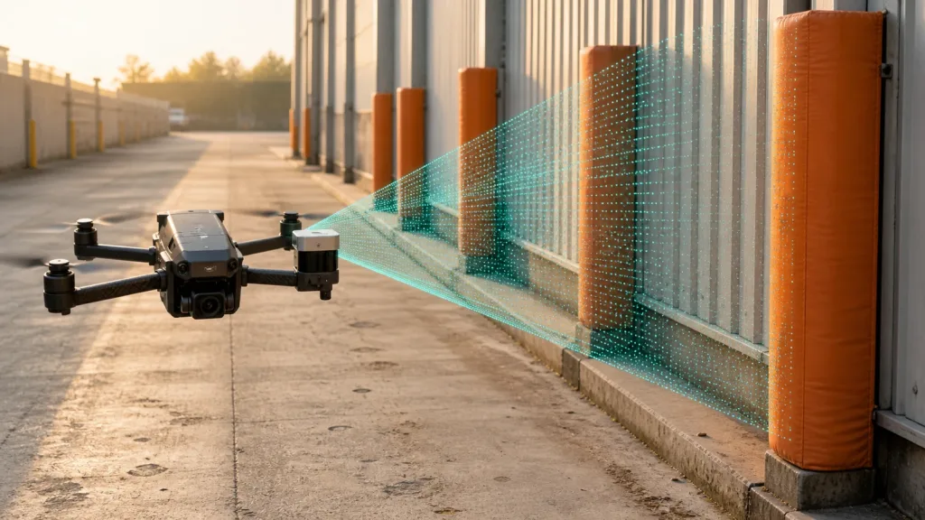
The current Featured product is the MRP-LD1 Drone LiDAR Sensor. Its documented numbers can inform a mounting review, but they do not establish a complete coverage layout. In particular, its listed 60° (H) × 45° (V) field of view is a directional module specification, not evidence that one installed module creates omnidirectional obstacle sensing.
| Documented MRP-LD1 parameter | Exported value | How to use it in this review |
|---|---|---|
| Technology | SPAD dToF; 940 nm VCSEL | Identify the module used in the evidence package. |
| Field of view | 60° (H) × 45° (V) | Plot one directional viewing region; validate its installed boundary. |
| Output | 40 × 30 | Record the configured output alongside the test capture. |
| Frame rate | 10 fps | Record the observed system timing; do not infer control performance from the sensor rate alone. |
| Interfaces | UART / UVC / UDP | Name the selected acquisition path and its receiving component. |
| Ranging capability | 0.5–25 m indoor; 0.2–8 m outdoor | State whether the proposed test lies within the documented condition-specific range. |
| Power and mass | 5 V; 1.2 W; 8 g | Keep the installed configuration and power review traceable. |
Use only the published values above in an RFQ or prototype comparison. Do not turn the table into a promise about aircraft range, collision avoidance success, certification, outdoor performance, or a whole-system safety margin.
Run a controlled yaw-sweep evaluation before a route test
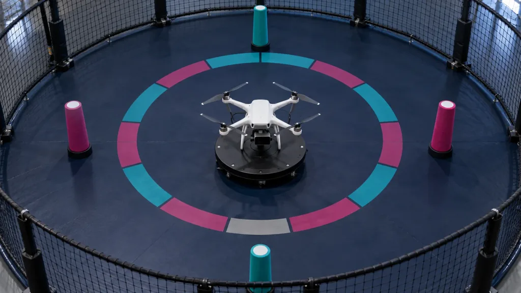
Illustrative application case: a netted indoor inspection mock-up
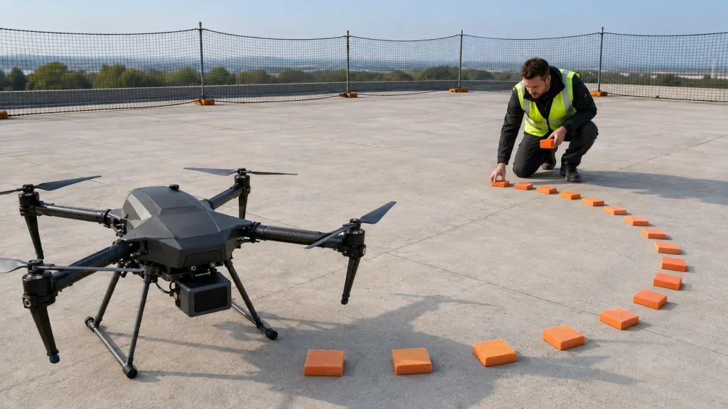
A team wants to inspect a short indoor service route where a UAV may rotate while moving past columns. They define a circular, netted test zone with target pylons at planned directions. With the final payload and mounts installed, they move the aircraft through preset yaw positions and boundary crossings. At each step, the log captures the configuration revision, sector under test, target condition, source that reported the observation, downstream recipient, and any operator-visible alert.
The useful outcome is not a universal pass statement. It is a bounded record: which sectors were exercised, which were intentionally excluded, where a hand-off needs another test, and which environmental or configuration limits must follow the aircraft into later evaluation. Teams can extend this sequence with the site’s earlier dToF UAV evaluation workflow.
Make the data and controller hand-off reviewable
A coverage plot is incomplete when it ends at the sensor. For every test run, preserve enough information to answer: which source produced the observation, which component received it, what state it produced, and who could see or override that state. Use a shared run identifier across the sensor capture, vehicle log, and operator record where the architecture supports it.
At minimum, a review row should include the airframe and mount revision, interface in use, source or stream name, time basis used by the test team, target direction, environmental note, downstream recipient, alert state, and observed result. The FAA DAA checklist similarly calls for DAA telemetry, displayed alerts, the pilot’s role, limitations, and data on timing from detection to alert and maneuver execution. That is a strong prompt for an integration review even when a prototype is not pursuing that FAA process.
Keep control authority explicit. A message arriving over UART, UVC, or UDP is not by itself an authorization to command a maneuver. The integration specification should say whether the receiving component informs a pilot, requests a controller action, inhibits a mode, or simply records an observation for review.
Common mistakes that make all-around claims fragile
- Using sensor count as proof of coverage: count assigned sectors and tested boundaries instead.
- Testing without the production-like mount: the mount, payload, and landing gear belong in the first evidence set.
- Hiding gaps with a broad diagram: mark unowned or untested regions plainly.
- Confusing detection with avoidance: record the receiving system, alert path, and expected action separately.
- Carrying an indoor result into another condition: retain lighting, target, environment, and configuration notes with the result.
- Describing the result as certification: keep an engineering review separate from operating approvals and safety claims.
RFQ and evaluation checklist
Before requesting an evaluation unit or approving a layout, ask the supplier and integration team to provide or confirm the following:
- The required sectors and any intentionally excluded directions in the airframe frame.
- Installed-view drawings or images that include payload and mounting hardware.
- Documented field of view, output, interface, condition-specific range, power, and mass for each directional module.
- The data consumer and expected behavior for every observation or alert.
- A boundary-crossing test plan, including how the team will log a gap, overlap, or hand-off anomaly.
- Conditions to be recorded: target, lighting, environment, vehicle configuration, and software/mount revision.
- The fallback or operator procedure when a sensor path is unavailable or uncertain.
- The authority that will decide whether the evidence is sufficient for the next test stage.
For documentation request details and integration material, use the site’s technical documentation resource. For U.S. operations, sensing hardware does not by itself change the applicable operating requirements; review the current FAA Part 107 overview and seek the appropriate operational guidance for the planned mission.
Turn the coverage claim into an evaluation brief
Bring a sector map, installed-view drawing, and intended data path to the discussion. Purpleriver can help you start an MRP-LD1 module evaluation around documented interfaces and parameters; your team should validate the complete aircraft-level coverage and operating fit.
Frequently asked questions
Does a wide field of view mean a UAV has 360-degree coverage?
No. A field-of-view value describes a directional sensor. Aircraft-level coverage still depends on installation, physical occlusion, sector boundaries, and the evidence from the actual configuration.
Can one MRP-LD1 module provide omnidirectional obstacle sensing?
The published MRP-LD1 field of view is 60° (H) × 45° (V). That is useful directional information, but it does not establish all-around vehicle coverage by one installed module.
What is a sector owner?
It is the named sensor and data path accountable for observing a defined direction or volume. A sector without an owner should be marked out of scope or assigned another testable solution.
Why test the installed mount instead of only the sensor on a bench?
The aircraft, bracket, payload, landing gear, and orientation are part of the final viewing geometry. A bench result cannot replace evidence from that installed configuration.
What should be logged during a yaw-sweep test?
Log the configuration revision, target direction and condition, sensor/source, receiving component, alert or control state, environmental notes, and result for every tested sector or boundary.
Does observing a target prove that the drone can avoid it?
No. Detection, alerting, decision logic, controller response, operator role, and the actual maneuver are separate parts of a system review.
How should a team document a coverage gap?
Mark its direction and altitude band, describe the cause or uncertainty, retain the test evidence, and state whether it is intentionally out of scope or requires a design change and retest.
Is this coverage review an FAA approval or a safety certification?
No. It is an engineering evaluation method. Operating permissions, regulations, and safety cases depend on the mission and the applicable authority.