Mobile-robot mounting and acceptance guide
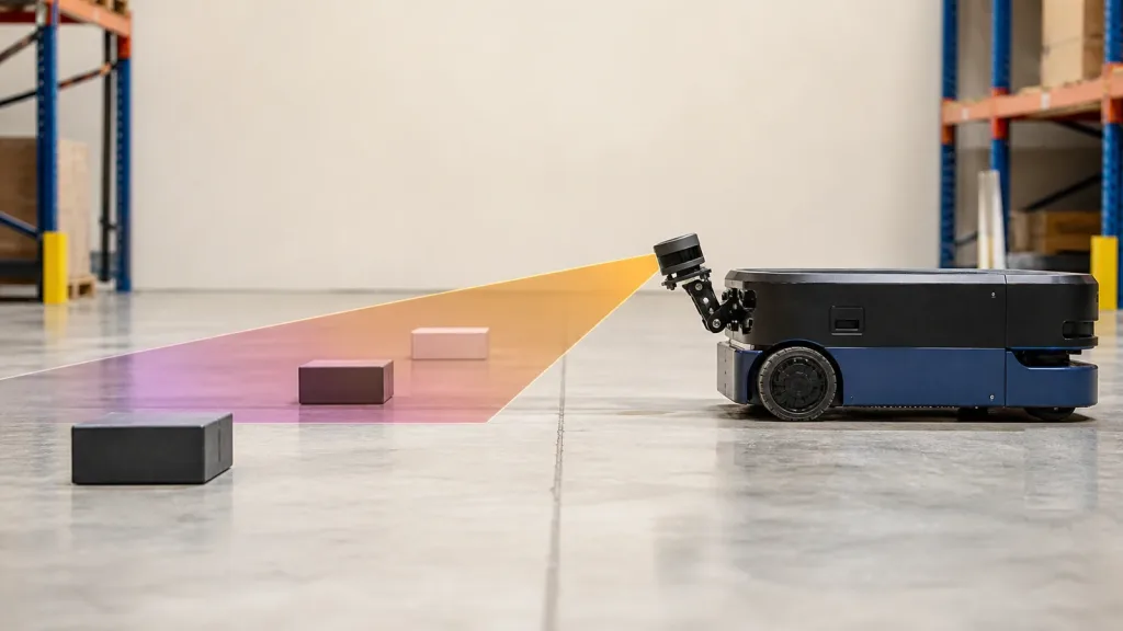
LiDAR for Robotics can pass a range check and still miss the low pallet toe directly ahead. That often happens after a compact sensor is moved higher for protection: the lower edge of its vertical field of view reaches the floor farther from the robot, leaving a near-floor strip that must be understood before the bracket is frozen.
The useful question is not simply “How far can the LiDAR measure?” It is “Which parts of the robot’s operating space create valid, timely points after mounting, calibration, filtering, and motion?” A range specification describes one boundary of the component. Low-obstacle coverage is a system result.
This guide turns that result into a repeatable engineering task. It combines a small geometry worksheet with physical targets, recorded point clouds, and middleware checks. The method applies to an AMR, service robot, inspection platform, or other ground robot with a forward-looking solid-state sensor.
1. Treat Coverage as Geometry Plus Pipeline
A front sensor can produce a visually convincing point cloud while the navigation stack ignores the points that matter. Four layers determine the usable obstacle zone:
- Optical geometry: mount height, pitch, vertical FOV, minimum usable distance, and robot-body occlusion determine where rays can go.
- Target response: size, reflectivity, incidence angle, ambient light, motion, and surface contamination influence whether a useful return exists.
- Data representation: coordinate frame, timestamp, point fields, invalid-point rules, and transform timing determine where software places the return.
- Navigation policy: height filters, range filters, marking, clearing, persistence, and stale-source behavior determine whether the return changes robot motion.
That is why a mounting review should include mechanical, perception, and navigation owners. The mechanical team can protect the sensor but unintentionally lift the view above a pallet foot. The perception team can remove floor clutter but also remove a short obstacle. The navigation team can configure a costmap correctly for the wrong sensor frame.
Use the site’s robotics 3D mapping solution for broader application context. For this task, keep one narrow acceptance question: can the installed sensor and pipeline preserve project-defined low obstacles from the raw capture to the motion layer?
2. Calculate the First-Pass Floor Intercept
Draw a side view before building brackets. Let:
hbe the optical center’s height above a level floor;pbe the optical axis pitch, positive downward;Vbe the full vertical field of view; andθdown = p + V/2be the lower-edge downward angle.
When θdown is greater than zero and less than 90°, the lower-edge ray meets the level floor at:
Dfloor = h / tan(θdown)
This is a ray-to-plane estimate. It assumes the stated optical frame, a level floor, ideal FOV limits, and no vehicle occlusion. It does not include the sensor’s minimum range, pixel sampling, calibration tolerance, target properties, filtering, floor slope, chassis pitch, or braking requirement.
A hypothetical worksheet
The following values are examples for planning—not MRP-LD1 performance claims. They use a 45° vertical FOV to show how height and pitch alter the lower-edge intersection.
| Mount height | Downward pitch | Lower-edge angle | Estimated floor intercept | What to test next |
|---|---|---|---|---|
| 0.30 m | 0° | 22.5° | 0.72 m | Check chassis occlusion and the minimum usable distance. |
| 0.45 m | 0° | 22.5° | 1.09 m | Place short targets inside, at, and beyond the predicted boundary. |
| 0.45 m | 7.5° | 30° | 0.78 m | Check whether the upper view still includes required structure. |
| 0.60 m | 10° | 32.5° | 0.94 m | Test robot pitch, floor transitions, and bracket tolerance. |
The estimate does not mean everything nearer than Dfloor is invisible. A tall target can cross higher rays before the lower edge reaches the floor, and a near target may enter the FOV above its base. Conversely, a very short object can remain below the view. Plot the actual target height as well as its distance, then verify it with physical samples.
Turn one number into a tolerance band
Repeat the calculation at the high and low limits of mount height, bracket pitch, sensor alignment, loaded chassis attitude, and floor slope. That produces a predicted band rather than a deceptively precise line. Your physical lane should bracket both ends of that band.
3. Compare Mounting Choices Before Freezing the Bracket
| Change | Likely geometric effect | New risk to inspect | Evidence needed |
|---|---|---|---|
| Mount lower | Moves the lower-edge floor intercept nearer | Chassis masking, impacts, spray, dust, and tighter near-range geometry | Installed self-view capture and low-target sweep |
| Pitch farther downward | Moves floor intersection nearer | Loses upper-scene coverage and increases floor returns | Pitch sweep with low and elevated targets |
| Mount higher | Can see over nearby low objects until they enter lower rays | Larger near-floor blind strip and larger alignment effect | Target-height-by-distance matrix |
| Add a protective window | Does not intentionally change the nominal FOV | Reflections, contamination, clipping, and changed ambient-light behavior | Final-window comparison in clean and contaminated states |
| Use a second viewpoint | Can reduce a geometric gap | Frame alignment, overlap policy, synchronization, bandwidth, and cost | Combined-coverage drawing and synchronized data test |
Choose a bracket only after the tradeoff is explicit. A more downward-looking mount is not automatically better: it may fill the cloud with floor points and remove useful sight lines to shelving, people, or overhanging structure. A level mount is not automatically better either. The correct setting is the one whose measured acceptance envelope covers the project’s obstacle set without breaking other perception tasks.
4. Use MRP-LD1 Parameters as Inputs, Not Conclusions
The Featured MRP-LD1 Drone LiDAR Sensor is a compact SPAD dToF option to evaluate for this workflow. Its published values can populate the first worksheet, but installed performance still needs target- and environment-specific testing.
| Published item | MRP-LD1 value | Mounting-test implication |
|---|---|---|
| Ranging principle and emitter | SPAD dToF; 940 nm VCSEL | Validate the final optical path, target set, and lighting. |
| Laser safety listing | Class 1 (FDA Recognized Eye-Safe) | Keep the supplied wording in component records; assess the complete robot separately. |
| Published range | Indoor 0.5–25 m; outdoor 0.2–8 m | Do not substitute maximum range for low-target coverage or stopping margin. |
| Ambient-light resistance | 80 klux | Include doorways, sun patches, target angle, and the final protective window. |
| Published accuracy bands | 0.2–1 m: ≤±3 cm; 1–5 m: ≤±5 cm; 5–8 m: ≤±10 cm; 8–15 m: ≤±20 cm | Set project tolerances within the relevant band and verify installed results. |
| Field of view | 60° horizontal × 45° vertical | Use 45° in the first-pass side-view worksheet, then verify calibrated usable rays. |
| Resolution and frame rate | 40 × 30 at 10 fps | Test whether small targets produce enough persistent points at robot speed. |
| Interfaces | UART, UVC, UDP | Select the host path, then measure timing and recovery at the navigation consumer. |
| Software support | Windows, ARM, Linux, Android | Confirm the exact API, data format, version, and target hardware during evaluation. |
| Electrical and mass | 5 V; 1.2 W; 8 g | Budget the installed cable, connector, bracket, protection, and power quality separately. |
| Temperature | Operating −20°C to 60°C; storage −30°C to 70°C | Validate the complete assembly over the project environment. |
The listing does not establish an IP rating, native ROS package, connector, end-to-end latency, or certified vehicle safety function. Put each needed item into the RFQ or acceptance plan instead of filling gaps with assumptions.
5. Build a Low-Obstacle Acceptance Lane
A taped lane converts the drawing into evidence. Use the final chassis, tires, payload state, window, bracket, cable routing, and compute load. Record raw data before adjusting perception filters.
- Declare the coordinate frame. Measure optical-center height and installed pitch relative to the robot base and test floor. Photograph the datum points and record bracket tolerances.
- Define the obstacle set. Select representative project targets by height, width, material, reflectivity, and approach angle. A hypothetical development set might include 40 mm, 80 mm, and 150 mm blocks, but the responsible team must choose the real acceptance objects.
- Bracket the prediction. Place each target before, around, and after the calculated floor-intercept band. Include the sensor’s applicable distance envelope and chassis overhang.
- Sweep the pitch. Capture identical stationary runs at several documented bracket positions. Compare valid-point count, target continuity, floor density, and upper-scene loss; do not tune the costmap yet.
- Add realistic motion. Repeat at controlled speeds, approach angles, turns, vibration states, lighting transitions, and floor ramps. Log acquisition and host times.
- Apply navigation filters. With the physical mount fixed, tune height/range handling and clearing behavior against the same lane. Cover or disconnect the sensor to test stale-source handling safely.
| Gate | Record | Project-defined pass rule | Owner |
|---|---|---|---|
| Installed geometry | Height, pitch, tolerance, FOV sketch, and self-occlusion image | Predicted coverage band matches the approved mounting envelope | Mechanical + perception |
| Raw target visibility | Unfiltered captures for every target, distance, angle, and light case | Target points meet the declared persistence and error criteria | Perception |
| Floor separation | Labeled floor and obstacle points through ramps and chassis attitude | Short obstacles remain while floor clutter stays within the processing budget | Perception + navigation |
| Motion robustness | Speed, turn, vibration, timestamps, dropouts, and point continuity | Usable observations remain inside the approved motion envelope | Systems test |
| Stale-source response | Stream interruption and recovery timeline | The robot enters the project-defined state within the configured timeout | Navigation + safety |
| Regression baseline | Hardware, bracket, calibration, software, and parameter versions | The affected lane cases rerun after a controlled change | Systems engineering |
Retain a short, representative dataset with the acceptance record. The point-cloud dataset evaluation guide explains what to examine before committing integration effort.
6. Connect the Physical Mount to the Data Contract
After the bracket is fixed, freeze the digital assumptions that make its geometry useful. The official ROS 2 PointCloud2 message definition includes the acquisition timestamp and coordinate frame in the header, organized dimensions in height and width, a field layout, and an is_dense indicator for invalid points. A handoff should state how the device output maps to those properties rather than merely saying “point cloud supported.”
Record at least:
- the sensor optical frame and the measured transform to the robot base;
- whether timestamps represent acquisition, reception, or publication and which clock produces them;
- depth units, point-field types, row/column order, invalid values, and confidence handling;
- organized-cloud dimensions and whether filtering changes their structure;
- UART, UVC, or UDP framing, loss detection, restart, and recovery behavior; and
- driver, calibration, firmware, host, and parameter versions.
If the team is deciding between a depth image and a cloud, read the depth map vs point cloud guide. For transport tradeoffs, use the interface selection guide. Interface names alone do not prove a native ROS driver or a complete navigation integration.
Make filter settings traceable to the lane
The official Nav2 Obstacle Layer documentation describes PointCloud2 observation sources and parameters such as sensor frame, minimum and maximum obstacle height, marking, clearing, obstacle range, and raytrace range. Tie each chosen value to a lane case. For example, prove that min_obstacle_height does not discard the shortest required target after transforms, and prove that clearing does not create false free space from invalid or occluded data.
Nav2’s official Collision Monitor documentation also exposes point-cloud height/range handling and a source_timeout that can stop a robot when a source becomes stale; setting the timeout to zero disables that check. Test the configured behavior by interrupting the stream in a controlled setup. Collision Monitor is an additional software-level mechanism, not a substitute for certified safety hardware or the project’s risk process.
Limited-FOV solid-state LiDAR also deserves orientation testing. A primary paper on solid-state-LiDAR SLAM describes limited FOV as a challenge and evaluates its method on a warehouse robot. That does not transfer the paper’s performance to the MRP-LD1; it supports a practical lesson: after choosing a mount, test turns and changing scene structure instead of validating only a straight, static aisle.
7. Worked Case: A Pallet Toe Below the Original View
Illustrative engineering scenario—not customer results: a compact warehouse AMR carries a front solid-state LiDAR at an optical-center height of 0.45 m. The sensor has a 45° vertical FOV and is initially level. The lower-edge calculation predicts a floor intersection at about 1.09 m.
The project requires detection of a low pallet toe before the robot reaches its declared operational margin. The team places representative toe targets at several distances around the predicted boundary. Raw captures show that the tall face becomes visible before its base, while the shortest edge is intermittent nearer the chassis. This prevents the team from treating the 1.09 m calculation as a binary blind-zone claim.
The team tests a documented 7.5° downward pitch. The simple estimate moves the lower-edge floor intersection to about 0.78 m. The new captures improve the near low-target view but add more floor points and reduce upper coverage. The team compares both mounts using the same obstacle matrix, turns, ramp transitions, and lighting cases, then selects the one that passes the combined low-target and upper-scene requirements.
Only after freezing that bracket does the team set height and range filters. It verifies the shortest target in the navigation layer, interrupts the stream to check stale-data response, and records the final transform, software versions, and test dataset. The result is a controlled mounting baseline—not a general promise that every low object will be detected.
8. Common Mounting and Coverage Mistakes
- Using maximum range as coverage. Range does not define the near-floor ray geometry, small-target visibility, or the robot’s response margin.
- Calculating from the enclosure edge. Measure from the optical center and use the calibrated optical frame.
- Freezing the bracket after one static screenshot. Sweep pitch, height, target angle, motion, lighting, and chassis attitude.
- Using the nominal FOV as a guaranteed valid boundary. Calibration, invalid edge pixels, masking, and the installed window can narrow usable coverage.
- Tuning filters before saving raw evidence. A clean costmap can hide whether the target was never measured or was removed later.
- Removing floor points with a large height threshold. The same setting can erase a required low obstacle after a transform or ramp change.
- Ignoring timestamps and stale data. Repeated old points can look stable while the current scene is unknown.
- Assuming platform support means a ROS package. Confirm the actual API, data format, driver scope, and version.
- Validating only straight aisles. Limited FOV, rotation, and sparse scene structure can change the useful observation set.
- Calling perception a certified safety function. Keep navigation features and the robot’s formal safety architecture distinct.
9. RFQ and Evaluation-Sample Checklist
Send the supplier an application envelope and a test question, not only “Will this LiDAR see low objects?” Include:
- robot type, speed envelope, stopping policy, proposed mount height/pitch, bracket tolerances, and chassis overhang;
- minimum obstacle height/width, target materials, approach angles, floor types, ramps, lighting, dust, and window conditions;
- required usable near/far distances, FOV, accuracy, persistence, invalid-data behavior, and dataset examples;
- selected UART, UVC, or UDP path, host hardware/OS, bandwidth, power, timing, restart, and recovery needs;
- calibration model, coordinate convention, timestamp semantics, depth units, point layout, and confidence/invalid values;
- current API, SDK, firmware, protocol, sample-data, and documentation resources needed for evaluation;
- bracket, window, thermal, vibration, ingress, connector, and cable questions not answered by the product listing; and
- acceptance matrix, required evidence, sample quantity, change notification, and regression expectations.
A useful response should let the mechanical team update the geometry worksheet and let the software team define a data contract. If an item is unknown, keep it as an evaluation gate rather than converting it into a presumed feature.
Review the Mount Before You Freeze the Robot Layout
Share your optical-center height, pitch range, lowest required obstacle, target distance, indoor/outdoor conditions, host platform, and preferred interface. Purpleriver can help you compare those requirements with the MRP-LD1’s published parameters and prepare the right questions for an evaluation sample.