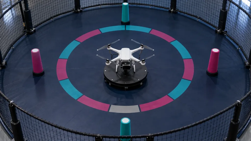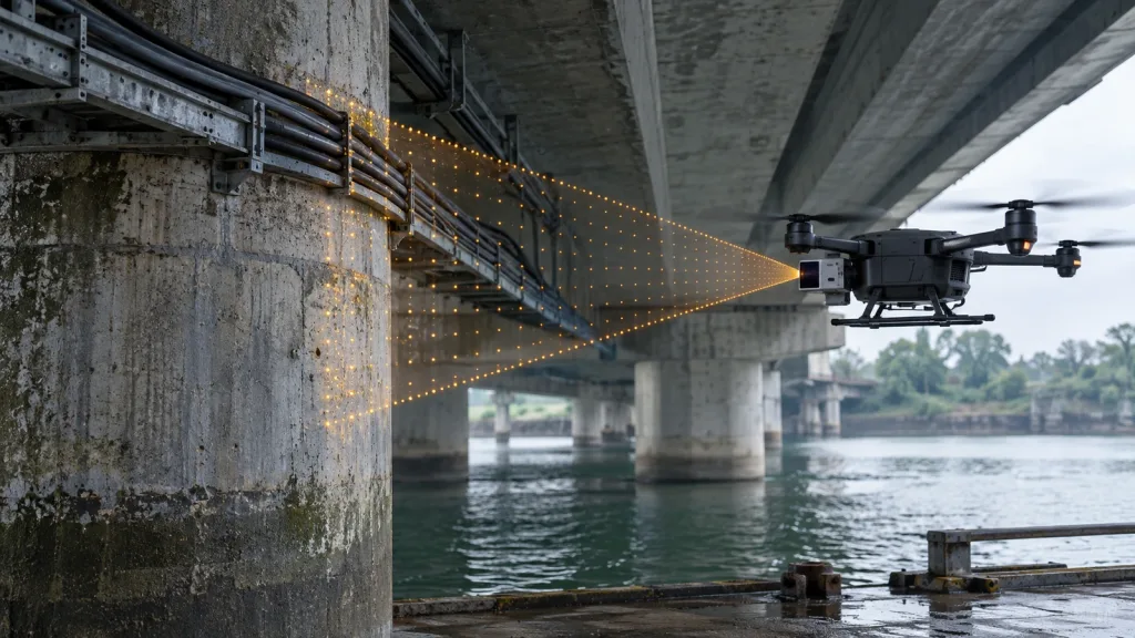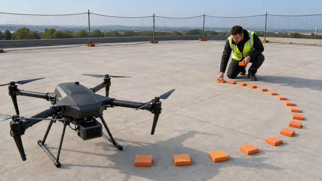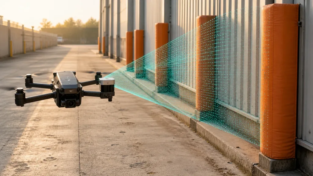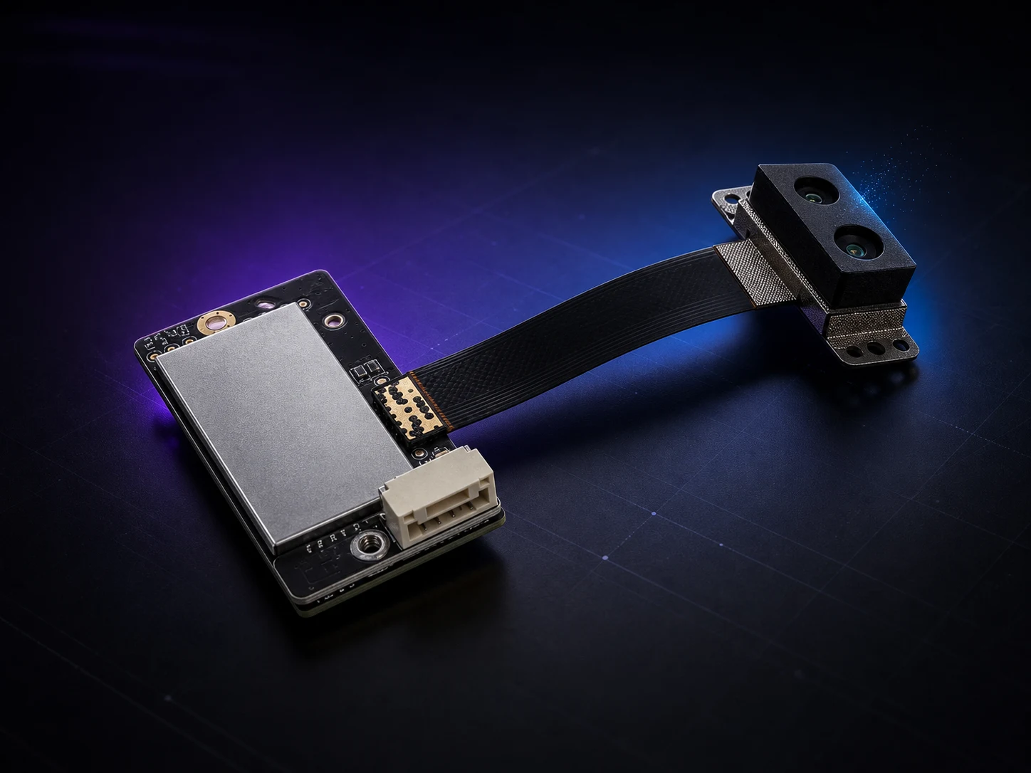
Drone collision avoidance is not a single-sensor feature. A working system combines sensing, host processing, decision logic and flight control, then validates the result against speed, target type, light, weather, mounting and failure behavior. LiDAR, cameras, ultrasonic sensors and radar each provide different evidence. The right question is not “Which sensor is best?” but “Which sensing inputs cover this mission’s risks?”
Four sensor families used for drone collision avoidance
| Sensor | Useful input | Typical strengths | What to validate |
|---|---|---|---|
| LiDAR / dToF | Direct range, depth image or point-cloud workflow data | Explicit depth measurements and compact 3D sensing options | Sunlight, reflectivity, target size, incidence angle, range, FOV and host timing |
| Camera / computer vision | Images, texture, color and semantic context | Rich scene information and object-recognition potential | Lighting, motion blur, low texture, calibration, compute load and depth method |
| Ultrasonic | Short-range echo distance | Simple proximity input for selected low-speed tasks | Beam shape, soft or angled surfaces, airflow, update rate and multi-sensor interference |
| Radar | Range and motion-related returns | Useful sensing in selected visibility and weather conditions | Resolution, clutter, antenna placement, near-field behavior and target classification |
Where compact dToF LiDAR fits
A compact dToF LiDAR module measures light travel time and provides depth information to a host system. That direct depth input can support forward obstacle awareness, downward altitude input, landing-zone evaluation or other task-specific sensing. It does not decide how the drone should turn, brake or climb. The host must interpret the data, apply the system’s rules and pass a command to the flight controller.
For the Purpleriver MRP-LD1, verified facts include an 8g module weight, 1.2W typical power, 60° horizontal by 45° vertical field of view, 40×30 depth output at 10fps, and UART, UVC or UDP interfaces. The listed indoor range is 0.5–25m; the listed outdoor range is 0.2–8m with up to 80Klux ambient-light resistance. These separate baselines must not be merged into a single all-condition range claim.
Where cameras fit
Cameras provide appearance and scene context that direct ranging sensors do not. A vision stack may identify an object category, lane, marker or landing feature. Stereo, structure-from-motion or learned models can estimate depth, but the result depends on calibration, texture, light, motion and processing. A camera and LiDAR can therefore be complementary: one contributes visual context while the other contributes direct depth measurements.
Where ultrasonic sensing fits
Ultrasonic sensing can provide simple proximity information at short range. It may suit controlled, low-speed tasks, but the beam pattern and target interaction must be tested on the real platform. Angled, soft or narrow targets can behave differently from a flat bench target. Rotor airflow, nearby ultrasonic devices and mounting geometry also belong in the validation plan.
Where radar fits
Radar can contribute range and motion-related information and may remain useful where optical visibility is difficult. Its suitability still depends on the antenna, frequency, processing, target and scene. Teams must test clutter, resolution, near-field behavior and airframe integration rather than treating the word “radar” as a universal solution. MRP-LD1 itself is a LiDAR module, not a radar product.
Why sensor fusion is a system decision
Combining sensors can reduce blind spots in one modality, but fusion adds calibration, timestamps, coordinate transforms, compute load and failure-handling work. Every stream needs a defined frame, clock and confidence model. The system also needs a rule for disagreement: for example, what happens when a camera sees an object but a depth sensor reports invalid points, or when the depth measurement changes faster than the controller can respond?
Do not begin with the assumption that more sensors automatically mean more safety. Begin with mission hazards, then assign evidence to each sensor and define how the host will detect stale, missing or conflicting data.
Collision-avoidance sensor selection checklist
- Define the direction: forward, downward, rear, lateral or overlapping sectors.
- Define the target set: walls, branches, wires, poles, people, vehicles, terrain or landing surfaces.
- Define the environment: indoor or outdoor, sunlight, low light, background, dust, weather and surface reflectivity.
- Define vehicle dynamics: speed, closing distance, braking or turning capability and allowed response time.
- Define the data path: interface, host, timestamps, filtering, inference and flight-control handoff.
- Define failure behavior: invalid data, timeout, occlusion, disagreement and degraded-mode response.
- Define evidence: logs, raw data, configuration, video, ground truth and an acceptance rule.
A bench-to-flight validation workflow
Start on a bench with known targets and confirm units, coordinates, frame rate, invalid-data meaning and interface stability. Move to a representative scene and vary distance, light, angle and target material one variable at a time. Mount the sensor on the real airframe and repeat the checks with enclosure, vibration, propellers, wiring and host-compute load included.
Only then should the team run restrained or tethered tests at conservative speed. Measure the complete chain from sensing to host decision to flight-controller response. Preserve difficult sequences for replay. Expand the flight envelope gradually and use a written abort rule. A successful demonstration is not the same as a validated operating envelope.