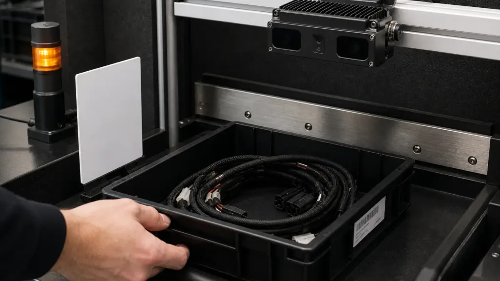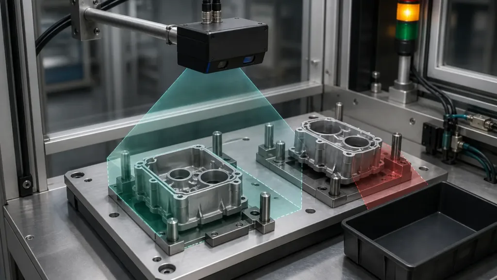
Industrial inspection 3D depth sensor projects usually fail for reasons that do not appear in a clean product demo. The inspection cell looks stable until reflective housings, locator pins, mixed-height trays, or a reject bin create depth holes and false pass/fail logic. Then the team discovers that the sensor can “see” the scene, but not in a way the QA workflow or controls stack can trust.
This guide is for factory automation engineers, machine builders, and technical buyers who need to validate a compact depth-sensing module before they approve a pilot line. It uses only the current Purpleriver featured-product export for product facts and pairs that with current authoritative sources on depth resolution, field-of-view screening, and output-quality evaluation.
| Quick answer | Approve an industrial inspection 3D depth sensor only after you prove zone coverage, reflective-part behavior, fixture blind spots, and QA handoff with replayable evidence from the real station geometry. |
|---|---|
| Best fit | Teams screening compact depth sensing for short-range inspection, part-presence confirmation, edge-clearance checks, and reject-bin monitoring. |
| Decision rule | If the team cannot define what counts as a valid detection, a nuisance event, and a controls-side usable result, the pilot should not be approved yet. |
Why an industrial inspection 3D depth sensor is useful for reflective parts and fixture-heavy stations
A compact depth sensor becomes useful when the station needs spatial evidence rather than a single distance value. STMicroelectronics currently positions direct-ToF sensing for industrial and robotics applications where compact integration and distance measurement matter, which is the right high-level category fit for inspection stations that must watch part edges, cavities, or approach zones rather than capture a full metrology-grade scan of an entire workcell.
The real engineering question is narrower. Can the sensor resolve the depth changes that matter at the specific target, keep coverage stable across the station geometry you can actually build, and hand usable data into QA or control logic without a fragile custom bridge? NIST’s April 27, 2026 publication on depth resolution is a useful reminder that depth resolution is not a marketing adjective. It is the smallest physical depth change the sensor can detect on a target, and that is exactly the kind of screening question a pilot line needs.
NIST’s 3D imaging roadmap pushes the same idea further. If your inspection decision depends on edges, corners, reflectivity changes, or stable output over time, then field of view, ambient conditions, output quality, robustness, and the ability to resolve geometric features all need to be tested deliberately. In practice, that means a compact sensor only becomes a real fit when you can answer these questions with evidence:
- Can the sensor see the part edges, slot openings, or bin transitions that actually determine pass or fail?
- Do fixture posts, locator pins, cable runs, or side walls create blind wedges in the station?
- Can the team replay questionable frames and explain why a part passed, failed, or produced an ambiguous result?
- Can the output be turned into a trustworthy event or measurement path for QA, PLC, or edge-compute logging?
If you need broader background first, Purpleriver already has a related article on industrial inspection with compact dToF LiDAR modules. This article is more specific: it focuses on what to prove before a pilot station is approved for reflective or geometry-sensitive parts.
Industrial inspection 3D depth sensor decision table for pilot-line screening
| Evaluation area | What to verify | Why it matters in inspection | Reject if |
|---|---|---|---|
| Target geometry | Depth separation between edges, holes, tabs, and cavity walls that matter to the decision | The station cannot make a reliable pass/fail call if the critical depth change is not resolvable | The feature you care about is too small, too shallow, or too occluded to detect consistently |
| Coverage and blind spots | Mounting height, side clearance, and any masked zones around fixtures or bins | False passes often come from geometry the sensor never saw, not from bad software | A locator post, guard, or tray wall hides a critical inspection area |
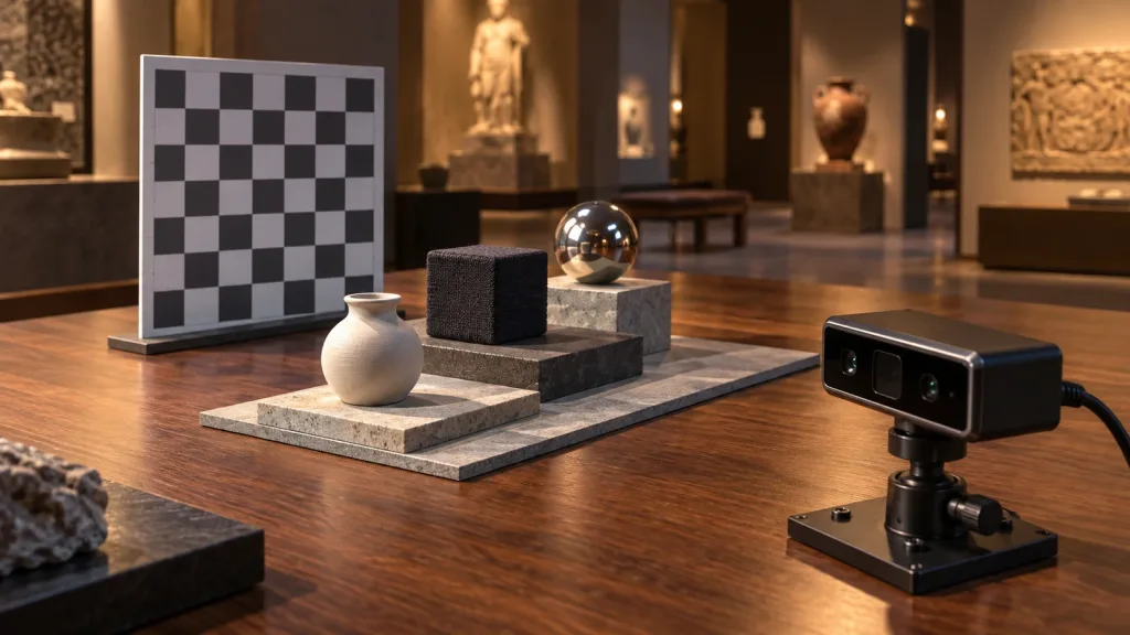
| Reflective-part behavior | Glossy metal, dark coatings, mixed finishes, and specular highlights under plant lighting | Reflectivity changes can create unstable depth or missing regions that break station logic | The station cannot maintain stable output on the real materials it must inspect |
| Output quality | Completeness of the depth map or point cloud, edge stability, and repeatability over repeated cycles | QA needs evidence that survives repeated production cycles, not one good frame | You cannot show repeatable results over the same part family and station setup |
| Handoff path | Whether the downstream system needs raw data, filtered depth, or a compact pass/fail event | A sensor win on the bench still fails if the station cannot consume the result cleanly | The required handoff depends on custom logic the production team will not maintain |
| Maintenance realism | Cleaning, threshold review, window contamination checks, and replay access | The pilot must show how the station stays usable after deployment, not just on day one | The workflow depends on manual tuning no line team can sustain |
Exact featured-product parameters to validate first
The current Purpleriver Featured WooCommerce product for this workflow is the LiDAR Drone Module – MRP-LD1 Solid-State dToF Sensor. If you are screening it as an industrial inspection 3D depth sensor, these are the only product facts this article treats as source truth.
| Parameter | Published value | Evaluation implication for inspection |
|---|---|---|
| Ranging principle | dTOF (Direct Time-of-Flight) | Validation should focus on real depth-change detection, not on 2D image appearance alone. |
| Scanning principle | SPAD (Single-Photon Avalanche Diode) | Use this as architecture context, then judge the station with measured output quality on your targets. |
| Wavelength | 940nm VCSEL | Confirm the station window, surface finish, and enclosure setup do not create avoidable optical problems. |
| Laser safety | Class 1 (FDA Recognized Eye-Safe) | Useful for screening, but it does not replace fixture, enclosure, or process-level risk review. |
| Range | Indoor 0.5-25m; outdoor 0.2-8m | For inspection, convert this into the exact target distances that matter at part, tray, and bin locations. |
| Ambient-light resistance | 80Klux | Still run plant-lighting tests rather than assuming the headline figure solves every mixed-finish scene. |
| Accuracy | 0.2-1m <= +/-3cm; 1-5m <= +/-5cm; 5-8m <= +/-10cm; 8-15m <= +/-20cm | Map these numbers to the minimum depth margin your station decision requires. |
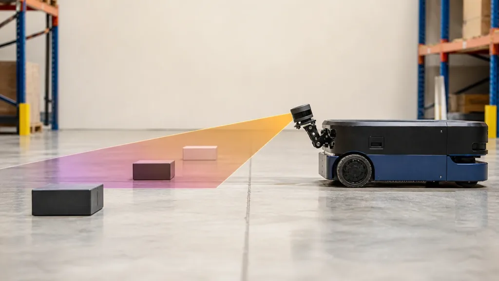
| FoV | 60 degrees (H) x 45 degrees (V) | Model whether one mounting position covers the fixture and reject path without a blind wedge. |
| Resolution / frame rate | 40 x 30 at 10fps | Check whether the station needs only robust zone logic or finer geometric discrimination than this grid supports. |
| Interfaces | UART / UVC / UDP | Pick the path that best supports capture, replay, and downstream decision logic. |
| Software support | Windows / ARM / Linux / Android | Useful when the bench workflow and deployed edge system differ. |
| Power / weight | 5V, 1.2W, 8g | Helpful when the station needs a compact bracket or slim protective enclosure. |
Validation workflow before pilot approval
1. Define the failure mode before you mount the sensor
Do not start with “we need 3D inspection.” Start with the exact production error the station must catch. Examples include a missing bracket tab, incomplete seating in a locator pocket, a part edge sitting above tolerance, or a reflective housing drifting too close to a reject chute wall. That definition tells you what depth change matters and what counts as success.
2. Draw the inspection volume, not just the field of view
Translate the sensor FoV into station geometry. Mark the part position, fixture walls, pin locations, reject bin lip, and any protective cover or bracket that can mask the scene. NIST’s roadmap is useful here because it treats FoV coverage, geometric-feature resolution, and output quality as separate evaluation concerns. A station can have a nominally acceptable FoV and still fail because the useful inspection volume is smaller than the station assumes.
3. Test reflective targets under the lighting you actually have
The 2025 paper Inline-Acquired Product Point Clouds for Non-Destructive Testing is a good reminder that 3D inspection becomes especially valuable when 2D systems struggle with reflectivity and complex geometry. Your job is not to copy that sensor architecture. It is to treat reflective and mixed-finish parts as a first-class screening variable. Run repeat tests with real housings, coated samples, and fixture backgrounds under production lighting rather than polished bench conditions.
4. Capture replayable evidence, not isolated screenshots
Every questionable station event should leave behind evidence the team can replay. That means storing the same kind of output you expect the downstream system to use, plus enough context to tie it to the fixture state and part position. Purpleriver’s documentation resources, sample datasets, and the guide on choosing the right LiDAR interface are the best internal checkpoints here.
5. Use a pass/fail sheet the controls and QA teams both accept
The pilot is not done when the perception engineer is satisfied. It is done when QA and controls agree on what the station must emit and how disputed frames will be handled. Define the expected output now: raw depth grid, filtered point cloud, measured edge distance, or a compact station event. If the downstream owner cannot maintain the path, the sensor is not ready for approval.
Interface, replay, and QA handoff planning
The product supports UART, UVC, and UDP, which is valuable because you can separate early validation from production integration. The safest rule is to pick the simplest path that still lets you prove the decision logic with replayable data.
| Integration topic | Questions to answer before approval |
|---|---|
| Bench capture | Which interface gives you the fastest reliable path to depth capture and replay on real parts? |
| Output form | Does the station need a depth map, point cloud, extracted edge measurement, or compact pass/fail event? |
| Replay workflow | Can the team review disputed results without rebuilding the scene from memory? |
| QA evidence | What data will be retained when a part is flagged, rejected, or manually reviewed? |
| Controls handoff | What exact signal, threshold, or message format will the PLC or edge system consume? |
| Maintenance | How will contamination, threshold drift, and fixture changeover be checked after launch? |
If your team is still deciding how much geometry it actually needs, Purpleriver’s article on depth map vs point cloud is helpful as a conceptual reset. Use only the output complexity your inspection workflow can really support. For fault isolation and bring-up, the existing guide on common LiDAR integration issues is also worth keeping close.
Realistic application case: machined-part inspection with a locator fixture and reject tray
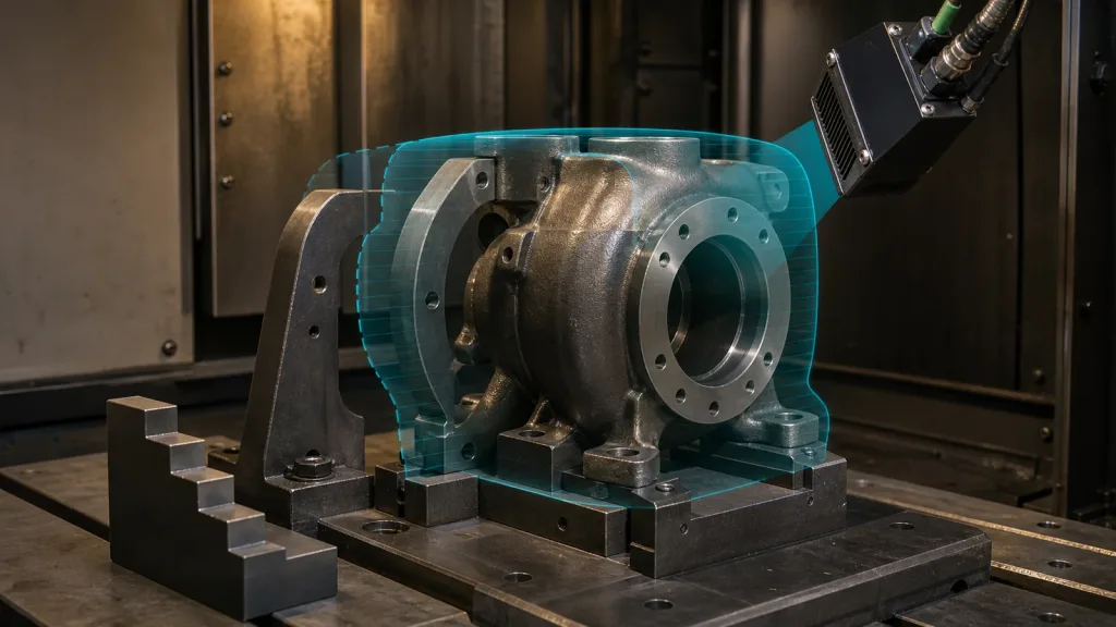
Consider a station that checks whether a machined housing is seated correctly in a locator fixture before the next process step. The station must confirm one outer edge, one recessed pocket, and the transition into a reject tray when a part fails. The part finish is semi-gloss, and the fixture contains posts that can block side visibility.
A practical evaluation sequence is:
- Mount the sensor at the real bracket height, not at the ideal demo angle.
- Measure which part edges remain visible with the fixture, posts, and tray installed.
- Run repeated cycles with acceptable and unacceptable seating positions.
- Check whether glossy surfaces or tray reflections produce depth holes or unstable edge readings.
- Confirm that the selected output can be retained as QA evidence and consumed by the station logic.
This is a realistic fit for a compact module only if the station can show repeatable evidence over repeated cycles, not just one convincing frame. If the scene still breaks on the real materials, the correct next move is to refine mounting, shielding, or workflow assumptions before you buy more hardware.
Common mistakes when screening an industrial inspection 3D depth sensor
- Approving the sensor after a clean demo frame instead of a repeated station workflow.
- Ignoring how fixture posts, tray walls, or enclosure lips create blind wedges.
- Testing only matte targets when the real parts are glossy, dark, mixed-finish, or partially reflective.
- Choosing a data format before QA and controls define what evidence they can actually use.
- Assuming a published ambient-light or accuracy figure replaces station-level validation.
- Failing to define how questionable frames will be replayed after the pilot launches.
RFQ and engineering evaluation checklist
| Checklist item | Why it belongs in the sample request or RFQ |
|---|---|
| Critical features to detect | Prevents the project from collapsing into a generic “3D inspection” request. |
| Part materials and finish conditions | Reflective and mixed-finish targets should shape the validation plan from the start. |
| Station geometry and mounting constraints | Blind spots usually come from mechanics before they come from algorithms. |
| Required output format | Keeps the sensor evaluation aligned with QA and controls ownership. |
| Replay and evidence retention needs | Makes disputed results explainable after the pilot starts. |
| Expected nuisance-event tolerance | Defines what level of false trigger is acceptable before production suffers. |
| Changeover and maintenance assumptions | Ensures the station can stay stable after launch instead of only during engineering tests. |
What approval should look like
An inspection pilot is ready when the team can show repeatable evidence on real parts, explain blind spots, and hand a stable result into the station workflow. Until then, the right next step is not a bigger promise. It is a clearer validation sheet.
If your team is evaluating a compact depth-sensing module for part presence, clearance, or reflective-feature checks, start with the featured MRP-LD1 product page and include your fixture geometry, target distances, and required handoff path when you use the contact page.