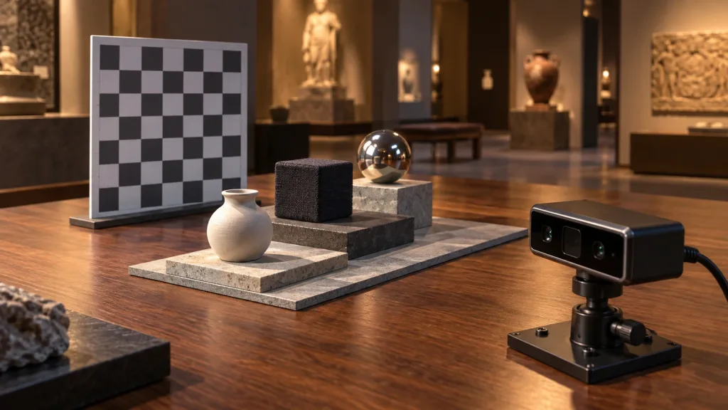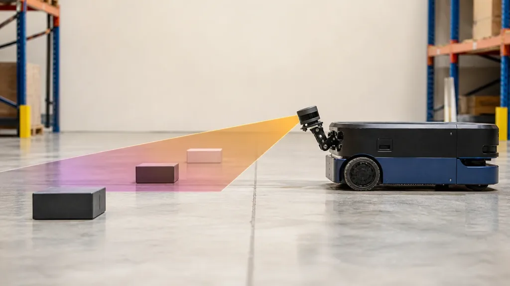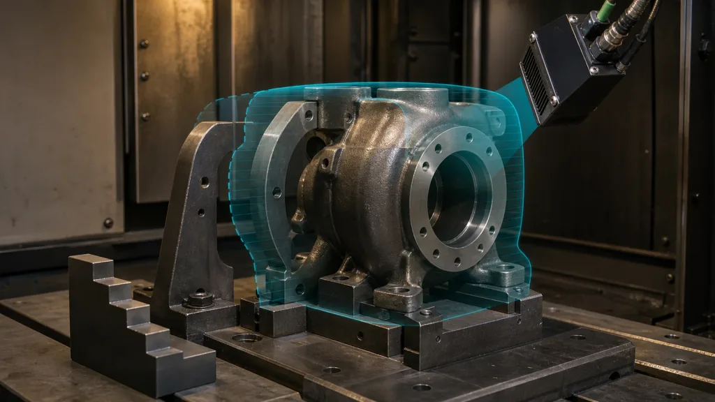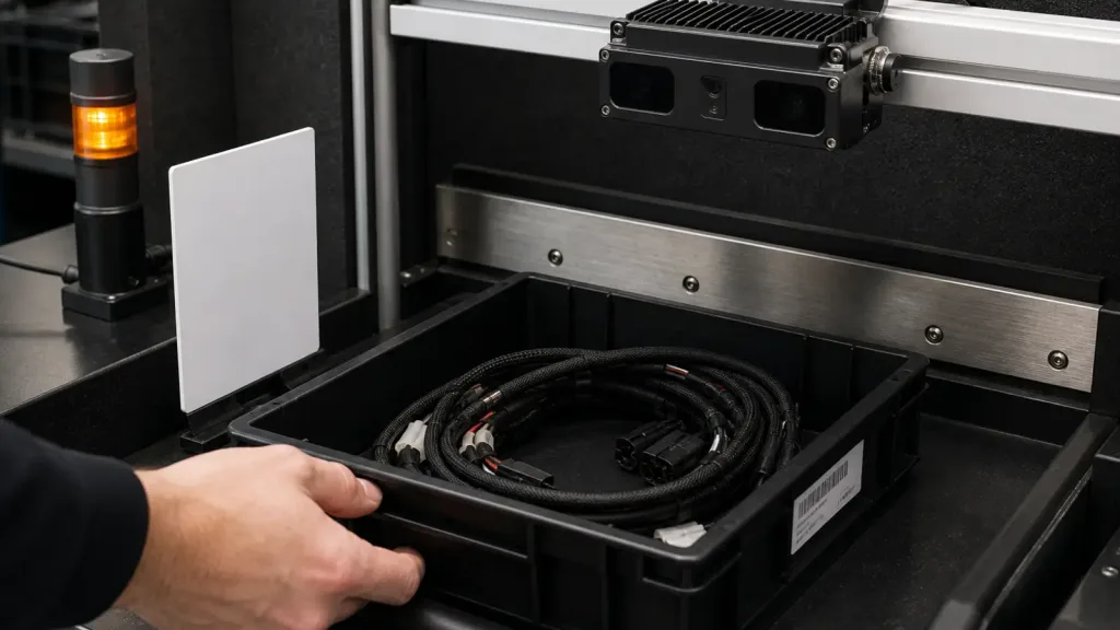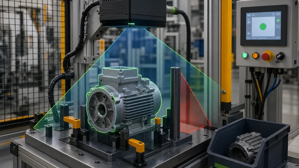
Industrial inspection solid state lidar projects usually fail after the demo, not during it. A compact module can look excellent over a clean sample part on a bench, then miss a reflective edge, lose coverage behind a fixture post, or hand off data that the PLC and QA logging stack cannot use without extra middleware.
This guide is written for automation engineers, machine builders, and technical buyers who need to decide whether a compact solid-state dToF module deserves a pilot inspection cell. The goal is not to admire a depth image. The goal is to prove that the sensing geometry, coverage, and data handoff are strong enough for a real industrial station.
| Quick answer | Use industrial inspection solid state lidar only after you prove the fixture geometry, reflective-part behavior, blind-zone coverage, and PLC or QA handoff in the exact pilot cell you plan to deploy. |
|---|---|
| Best fit | Teams validating compact 3D sensing for pass-fail presence checks, edge-clearance checks, and short-range fixture inspection in a controlled factory station. |
| Decision rule | If you cannot define a repeatable pass-fail condition for real parts and replay the evidence into your controls workflow, the module is not ready for pilot approval. |
Where industrial inspection solid state lidar fits best
The strongest use case for industrial inspection solid state lidar is not full metrology replacement. It is fast, short-range spatial verification when a station needs more than a single beam but less than a heavy machine-vision rebuild. That usually means confirming part presence, checking whether an edge or opening is visible from a known mounting position, or proving that a reject path and fixture geometry stay clear enough for the next cycle.
That framing matters because engineers often inherit the wrong expectation. The Reddit discussion surfaced in the brief shows a recurring concern: people hear “solid-state” and immediately jump to reliability and category comparisons, but they still need a concrete way to evaluate field coverage and practical limits. Primary sources support that caution. NIST’s work on 3D perception systems for robotic assembly stresses measurable evaluation in inspection and automation contexts, and research on solid-state LiDAR repeatedly notes that smaller field of view and scene-specific constraints can become the real bottleneck if the workflow is not validated early.
So the right first question is simple: what must the station decide in one cycle? If the cell only needs to confirm whether a reflective housing is seated correctly in a locator and whether a clearance region stays open for the next motion step, a compact module can be a practical fit. If you need micron-level dimensional certification or a wide multimeter-scale scene without repositioning, this sensor class should be screened more cautiously.
If you want broader background first, Purpleriver already has related material on industrial inspection with compact dToF LiDAR modules and quality inspection notes for solid-state LiDAR modules. This article focuses on what a pilot-cell approval workflow should prove.
Industrial inspection solid state lidar decision table for pilot-cell screening
| Evaluation area | What to verify | Why it matters | Reject if |
|---|---|---|---|
| Coverage geometry | Mounting height, field-of-view fit, blocked corners, and masked regions behind posts or tooling | A pilot cell fails if the part feature or reject path lives inside a blind zone | The must-see edge or opening is not visible from the mounting position you can actually build |
| Reflective-part stability | Repeatability on machined, coated, or mixed-finish surfaces | Shiny or dark surfaces often break demo-only assumptions | The pass-fail threshold shifts materially across repeat trials on production-like parts |
| Cycle-fit data output | Whether the station needs a depth grid, point cloud, event flag, or replay log | The downstream controls burden can be larger than the sensing burden | The required output cannot be consumed without fragile custom middleware |
| Environmental fit | Plant lighting, cable routing, enclosure layout, and maintenance access | A workable lab setup often collapses during real station packaging | Stable operation depends on a mounting or service approach the line team will not support |
| Evidence and replay | How operators and QA engineers inspect failures after the fact | A pilot cell must explain false rejects and missed detections quickly | No usable replay path exists for real reject events |
Exact featured-product parameters to validate first
Purpleriver’s current WooCommerce Featured product for this workflow is the LiDAR Drone Module – MRP-LD1 Solid-State dToF Sensor. These are the published facts that can be used in evaluation planning. Everything else must be proven in your own test cell.
| Parameter | Published value | Inspection-cell implication |
|---|---|---|
| Ranging principle | dTOF (Direct Time-of-Flight) | Screen it for spatial decision tasks rather than single-threshold distance-only logic. |
| Scanning principle | SPAD (Single-Photon Avalanche Diode) | Useful when you need a compact solid-state sensing approach with depth output. |
| Emitter wavelength | 940nm VCSEL | Review cover-window, fixture, and surface assumptions in the real station build. |
| Laser safety | Class 1 (FDA Recognized Eye-Safe) | Helpful for product screening, but still document the real mounting and guarding context. |
| Range | Indoor 0.5-25m; outdoor 0.2-8m | Convert this into the exact fixture distance and reject-path distances that matter in your station. |
| Ambient-light resistance | 80Klux | Still test under actual plant lighting and mixed-surface conditions. |
| Accuracy | 0.2-1m ≤ ±3cm; 1-5m ≤ ±5cm; 5-8m ≤ ±10cm; 8-15m ≤ ±20cm | Judge whether those ranges support presence, clearance, or coarse geometry checks, not precision metrology. |
| FoV | 60°(H) × 45°(V) | Build a simple coverage sketch before hardware approval, especially around fixtures and bins. |
| Resolution / frame rate | 40 × 30 at 10fps | Works best when the station needs robust spatial evidence, not fine-resolution surface measurement. |
| Interfaces | UART / UVC / UDP | Choose the handoff path that matches your controls stack and replay workflow. |
| Software support | Windows / ARM / Linux / Android | Useful when a pilot cell needs a PC bench rig before embedded integration. |
| Power / weight | 5V, 1.2W, 8g | Helpful for compact mounting on a bracket, hood, or station mast. |
A practical validation workflow before you approve a pilot cell
Use the workflow below before you buy more than one or two pilot units. It keeps the evaluation grounded in the station decision you actually need to automate.
- Define the pass-fail event in plain language. Example: “The housing is fully seated in the fixture, its left edge is visible, and the reject chute is clear before the clamp releases.” If the event is vague, the sensing test will also be vague.
- Draw the real station geometry. Mark the part, fixture posts, operator access side, cable entry, reject bin, and any moving hardware. A compact solid-state LiDAR with limited field coverage should be judged against that geometry first.
- Build a visibility matrix. For each critical feature, record whether it is fully visible, partially masked, or invisible from the intended mount point. Research on solid-state LiDAR repeatedly warns that narrower or structured FoV can become the real integration constraint.
- Run repeat trials on real or production-like surfaces. Use bright metal, darker coated parts, and any mixed-finish part families you expect on the line. The goal is not to hunt for one pretty frame. The goal is to measure whether the same decision survives repetition.
- Log failures in a replayable format. If you cannot replay the event through a workstation or bench script, the controls team will struggle to trust the rejection logic later.
- Verify the handoff path. Decide whether the pilot will trigger on simple event states, a processed region result, or a host-side decision derived from streamed data.
This same discipline also helps when you compare the station against other site resources such as documentation and sample datasets. If the pilot cannot define its acceptance evidence before sample arrival, the problem is usually the workflow, not the sensor.
Interface, data, and integration planning
Integration mistakes are one of the fastest ways to waste a solid inspection concept. Purpleriver’s featured product supports UART, UVC, and UDP, so the better question is not “which interface exists?” It is “which interface keeps the controls workflow understandable?” Purpleriver also already covers broader troubleshooting in common LiDAR integration issues and interface tradeoffs in UART, UVC, or UDP: choosing the right LiDAR interface.
| Interface path | Best pilot use | Risk to watch |
|---|---|---|
| UART | Compact event-driven bench tests and embedded proof-of-concept logic | You can lose debugging speed if the validation team needs richer replay visibility. |
| UVC | Fast workstation bring-up and visual replay during evaluation | Teams sometimes stop at the demo stage and never define the final control handoff. |
| UDP | Higher-throughput lab logging or networked station experiments | It adds network behavior and parsing work that may not belong in a first pilot. |
For many factory pilots, the most pragmatic path is to begin with the interface that makes replay easiest, then collapse to the leanest deployment path once the pass-fail logic is stable. That is consistent with system-level guidance from Texas Instruments and measurement-oriented guidance from NIST: prove the sensing and evaluation method first, then harden the deployment path.
Realistic application case
A motor-housing inspection station is checking whether a reflective machined housing is seated correctly in a locator nest before a press-fit and whether the reject chute remains clear if the part is diverted. The line team does not need precision dimensional metrology from the LiDAR module. It needs a reliable answer to three questions:
- Is the part present in the intended fixture position?
- Is the visible edge profile consistent enough to suggest correct seating?
- Is the reject path open before the next cycle starts?
In this case, a compact solid-state module can be reasonable if the fixture post does not hide the seating edge, the reflective surface does not produce unstable decisions across repeated trials, and the output can be logged or replayed when a reject occurs. If any of those checks fail, the pilot should stop before procurement expands.
Common mistakes
- Approving the module after a single clean demo on one part finish instead of repeated trials on real production-like surfaces.
- Ignoring blind zones created by brackets, fixture posts, or bin walls until mechanical design is already fixed.
- Assuming a depth image is automatically useful to a PLC or QA station without defining the downstream event format first.
- Using published range and FoV values as proof of station fit without drawing the exact pilot geometry.
- Skipping replay and failure logging, which makes every false reject feel random to the line team.
RFQ and pilot-approval checklist
| Checklist item | Approve only when |
|---|---|
| Station decision is defined | The team can state the pass-fail event in one sentence. |
| Coverage sketch exists | All must-see features and reject-path zones are mapped from the intended mount point. |
| Reflective-part trial is complete | Real or representative parts have been tested repeatedly under plant-like lighting. |
| Interface path is chosen | The pilot knows whether UART, UVC, or UDP is the working evaluation path. |
| Replay workflow exists | Operators or engineers can inspect a failed cycle after the fact. |
| Maintenance fit is acceptable | Cable routing, cleaning access, and bracket reach are practical for the station owner. |
Move from a sensor demo to a requirement-led pilot
If your team is screening a compact LiDAR module for a real inspection station, start with the station decision, the coverage sketch, and the handoff format you need to prove. Then compare those requirements against the published MRP-LD1 facts and request the smallest pilot that can produce replayable evidence.
That approach gives Purpleriver or any internal review team a much better starting point than a generic request for “an industrial LiDAR.”