Solid-state laser radar becomes interesting for a robotics team when the platform cannot tolerate the maintenance, packaging, or vibration penalties of a moving-part sensor, but still needs dependable near-field perception. The wrong buying pattern is to stop at the architecture label. The right one is to check whether field coverage, blind-zone behavior, and data flow still hold up on the real mobile robot you plan to ship.
This guide is written for an integration lead or technical buyer evaluating a compact sensor for a service robot, inspection robot, or small AMR that crosses joints, ramps, cable covers, or other vibration-producing surfaces. It turns the phrase solid-state laser radar into a shortlist workflow you can actually use before requesting samples.
| Quick answer | Shortlist solid-state laser radar when your platform needs compact packaging, no moving scan assembly, predictable host integration, and a clear way to validate field coverage and blind zones under real motion. |
|---|---|
| Best fit | Robotics teams screening sensors for small indoor mobile platforms that must detect shelves, pallet corners, corridor obstacles, or docking geometry without overloading payload, power, or enclosure design. |
| Decision rule | If the vendor cannot connect architecture claims to a repeatable coverage test, a vibration-exposure plan, and a usable output path, the sensor is still a concept for your program rather than a shortlist-ready option. |
Why solid-state laser radar matters on mobile robots
The value of solid-state laser radar is not that it sounds newer. It is that many compact robots need a depth sensor that is easier to package, easier to protect, and easier to keep aligned than a bulkier spinning assembly when the chassis crosses rough floor features or operates inside tight enclosures. Recent solid-state LiDAR research also shows why teams must stay practical while evaluating that promise. Work on lightweight SLAM for solid-state LiDAR highlights the appeal of compact sensing on smaller robots, while field studies of difficult environments show that limited field of view can become a real localization and mapping constraint if the deployment geometry is not planned carefully.
That is exactly where buyers need a better framework. The engineering question is not "solid-state or spinning" in the abstract. It is whether the solid-state option gives enough usable coverage and stable data for the specific robot decision you care about: obstacle stop, corridor edge awareness, docking alignment, or protected-zone entry. NIST's 3D imaging roadmap for robotics is helpful here because it keeps the evaluation anchored to measurement volume, repeatability, latency, and output usefulness instead of marketing vocabulary alone.
Reader intent from public Reddit search results reinforces the same point. People keep asking why teams trust solid-state LiDAR and whether reliability or range claims are real. That concern is useful editorial input, but it is not technical proof. The publishable answer has to come from your evaluation workflow, the product facts you can verify, and current primary sources on what solid-state systems do well and where they still introduce trade-offs.
If you need a broader background comparison before this shortlist stage, start with solid-state LiDAR vs mechanical LiDAR. This article picks up at the next step: what a robotics buyer should verify before ordering hardware.
Shortlist matrix for mobile-robot buyers
| Screening question | Why it matters | Pass signal | Red flag |
|---|---|---|---|
| Does the sensor see the exact obstacle volume the robot must react to? | Field of view only matters if it covers the pallet edge, wall return, rack leg, or docking target that drives the control decision. | The vendor can map usable coverage against your stand-off distance and mounting height. | You only receive one headline FoV number and no deployment geometry. |
| Can the packaging survive vibration and enclosure constraints? | Rough floors, ramps, thresholds, and protective covers create more risk than a clean bench demo suggests. | The evaluation plan includes the real mount, bracket orientation, and floor disturbances the robot will see. | The demo is hand-held or bench-top with no motion or bracket discussion. |
| Will blind zones stay acceptable at the robot’s approach speed? | Near-field misses matter more than impressive maximum range on compact mobile robots. | The team can define a measurable stop zone and verify coverage there. | The approval language talks about "good range" but never defines the true decision zone. |
| Can the host ingest and review the data without delaying the project? | Shortlists collapse when a sensor streams data that nobody can parse or replay quickly on the target stack. | The output path, frame format, and first logging workflow are known before sample approval. | The interface plan is left until after procurement. |
| Does the architecture improve the robot’s decision quality enough to justify evaluation effort? | A compact module is only worth the switch if it produces clearer evidence for your real obstacle or navigation task. | The team can explain what improves: coverage, packaging, reaction distance, or deployment simplicity. | The architecture is being shortlisted because it sounds modern. |
Exact featured-product reference parameters
The featured Purpleriver module below is the factual reference baseline for this article. Use it to compare architecture claims against a sensor with known interfaces, power, weight, and supported use cases.
| Product | LiDAR Drone Module – MRP-LD1 Solid-State dToF Sensor |
|---|---|
| Ranging principle | dTOF (Direct Time-of-Flight) |
| Scanning principle | SPAD (Single-Photon Avalanche Diode) |
| Emitter | 940nm VCSEL |
| Laser safety | Class 1 (FDA Recognized Eye-Safe) |
| Range | Indoor 0.5-25m; outdoor 0.2-8m |
| Ambient-light resistance | 80Klux |
| Accuracy | 0.2-1m <= +/-3cm; 1-5m <= +/-5cm; 5-8m <= +/-10cm; 8-15m <= +/-20cm |
| Field of view | 60 degrees (H) x 45 degrees (V) |
| Resolution / frame rate | 40 x 30 at 10fps |
| Interfaces | UART / UVC / UDP |
| Software support | Windows / ARM / Linux / Android |
| Power / weight | 5V, 1.2W, 8g |
Those facts make the module useful as a shortlist control. If another solid-state laser radar candidate needs a much larger enclosure, a harder host path, or a less defined evaluation workflow, then the architecture premium may not be helping your robot program. If it materially improves your coverage or near-field decision quality, then the extra effort may be justified. The point is to compare evidence to evidence, not concept language to a real product page.
A field-first evaluation workflow
- Write down the robot decision the sensor must support. Examples include shelf-edge stop, corridor obstacle warning, ramp-entry slowdown, or docking alignment.
- Map the sensor volume against the real mount. Include bumper height, mast offset, protective cover, bracket angle, and the first obstacle distances that matter.
- Create a blind-zone test before the sample arrives. The team should know which floor-level or side-angle misses would be unacceptable.
- Run vibration-relevant checks early. A compact robot that crosses thresholds or steel plates can expose data instability long before a long-range metric becomes relevant.
- Approve or reject the sample using replayable evidence. A one-minute demo clip is not enough; the buyer needs logs, scene conditions, and a pass/fail conclusion tied to the robot task.
This workflow keeps the discussion grounded in the deployment, not the architecture label. It also complements existing site resources on what to confirm before requesting an evaluation sample and on how to diagnose integration issues once data starts flowing.
Interface, data, and integration planning
Many buyers underestimate the output-path question. On a small robot, the sensor is only useful if the host can ingest, review, and replay the data quickly enough for the evaluation cycle to stay productive. That is why interface selection belongs in the shortlist stage rather than after procurement. Purpleriver's reference module supports `UART`, `UVC`, and `UDP`, which gives the team several paths to first data capture. If your stack still needs a refresher on those trade-offs, review UART, UVC or UDP.
You should also define what representation the robot actually needs. Some projects say they need "LiDAR" when the real requirement is a reliable near-field depth map for obstacle logic. Others truly need richer point-cloud-style review during evaluation. That distinction changes how you judge frame size, replay tooling, and host workload. Purpleriver's guide on depth map vs point cloud is useful here because it prevents the team from treating output richness as an automatic advantage.
| Integration topic | Question to answer before approval |
|---|---|
| Mounting geometry | Will the bracket, bumper, shell, or protective window clip the useful view? |
| Power path | Can the 5V supply remain stable during drive-current changes, braking, or accessory switching? |
| First logging path | Is UART, UVC, or UDP the fastest route to replayable data on your bench? |
| Host environment | Will the first evaluation run on Windows, Linux, ARM, or a mixed setup? |
| Review workflow | How will misses be inspected: live view, recorded depth frames, or exported logs? |
| Control handoff | What latency is acceptable between a hazard entering the decision zone and the robot action? |
If your use case is closer to mapping than simple stop-zone protection, keep the workflow aligned with robotics mapping for AMR and service robot navigation. That article is broader than this buying guide; the present piece stays focused on shortlisting and validation before you spend engineering time.
Realistic application case: a service robot crossing thresholds in a hospital back corridor
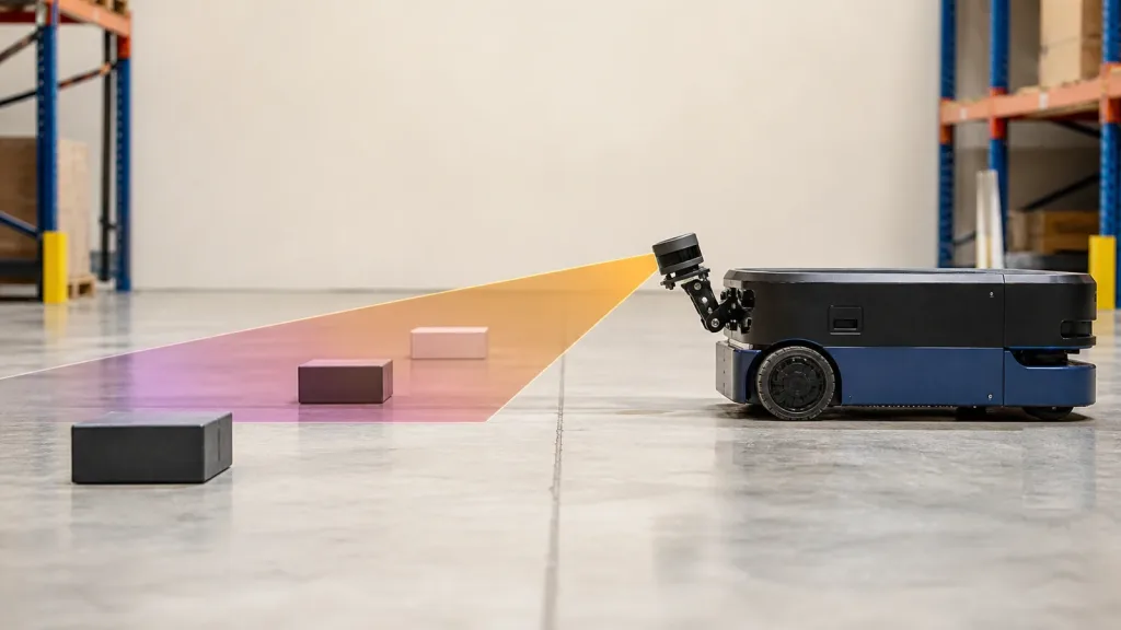
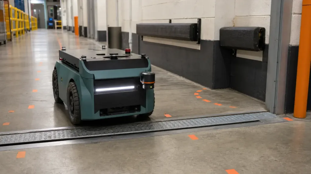
Consider a small service robot that moves supplies through a back corridor with wall-mounted cabinets, stainless carts, and frequent metal thresholds between rooms. The robot does not need a glamorous perception stack. It needs stable near-field awareness while the chassis shakes over floor joints and the enclosure leaves little room for a large external sensor.
A solid-state laser radar shortlist would be evaluated in five steps:
- Mount the candidate on the intended front corner or center mast, not on a temporary bench fixture.
- Mark the true stop zone on the floor and on nearby wall returns so the team can judge whether blind zones appear during approach.
- Run repeated passes over thresholds, cable covers, and slight ramps while logging the depth output.
- Replay the data after each pass to see whether floor disturbance, enclosure vibration, or protective covers reduce usable perception.
- Approve the sample only if the logs show repeatable coverage in the real corridor geometry, not just static success in a clean lab scene.
This is a realistic buyer workflow because it ties the architecture to a robot task. It does not assume that "solid-state" automatically solves everything. It asks whether the sensor helps the robot make a better decision in the exact environment the program must support.
Common mistakes
- Treating solid-state laser radar as a self-proving category instead of a candidate that still needs deployment evidence.
- Using maximum range as the main buying metric when the actual risk lives inside the first few meters around the robot.
- Skipping blind-zone mapping because the field-of-view number looks wide enough on paper.
- Approving a sensor from a bench demo without running threshold, ramp, or vibration-relevant passes.
- Leaving the output path undefined until after the sample arrives.
- Comparing two sensors at different levels of evidence instead of using a consistent shortlist matrix.
RFQ checklist
| Ask for | Why it belongs in the RFQ |
|---|---|
| Coverage example at your mounting height | Prevents a generic FoV claim from replacing the real obstacle volume. |
| Blind-zone explanation near the bumper or floor plane | Surfaces the exact edge cases that can break a mobile robot safety margin. |
| Frame format and interface notes | Lets the engineering team judge the time-to-first-data path before purchase. |
| Evidence under real ambient conditions | Shows whether reflective carts, bright spill light, or dark flooring change behavior. |
| Mechanical envelope and protection assumptions | Protects the program from bracket, shell, or cover conflicts discovered too late. |
| Repeatable sample outputs or logs | Makes the buying decision depend on replayable evidence instead of a live demo only. |
| Supported host environments | Clarifies whether evaluation can start immediately on your Windows, Linux, or ARM bench. |
| Technical follow-up path | Keeps the vendor discussion tied to your robot geometry and acceptance criteria. |
Use a robot-task scorecard before you order a sample
If your team can already define the stop zone, the mounting geometry, the likely blind-zone risks, and the first data path, you are ready to evaluate a solid-state option seriously. If those answers are still vague, tighten the scorecard before more hardware enters the program.
Purpleriver's MRP-LD1 reference module, product page, and documentation resources give buyers a practical baseline for that conversation. Start from the actual robot geometry and data needs, not from generic architecture language.
Review the featured module, then use the documentation hub to frame a sample request around your real mobile-robot acceptance criteria.