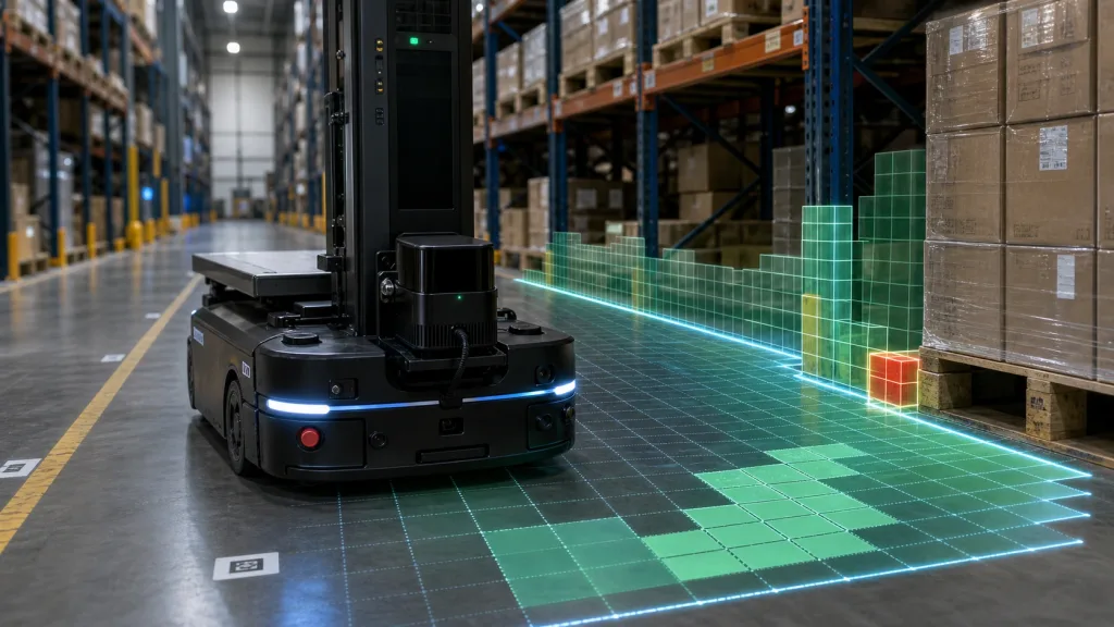
3D LiDAR sensor projects for warehouse AMRs usually fail long before the robot moves its first pallet. The weak point is not the idea of depth sensing itself. It is the gap between a promising sensor demo and the evidence a robotics team needs to prove that aisle coverage, rack-end visibility, blind-spot behavior, and host data flow are good enough for real mapping and obstacle handling.
This guide is written for robotics integration leads, AMR solutions engineers, and technical buyers who need a practical workflow for screening a compact sensor before they commit bench time, mounting hardware, or a broader warehouse pilot.
| Quick answer | A 3D LiDAR sensor is worth integrating into an AMR mapping program only after the team verifies aisle-width coverage, near-field blind spots, replayable depth data, and a clean handoff into its navigation stack. |
|---|---|
| Best fit | Compact indoor robots that need short-range depth awareness for aisle mapping, rack-end obstacle checks, docking approach validation, or protected-zone detection. |
| Decision rule | If the team cannot describe the exact mapping zone, the host interface path, and the pass/fail evidence for blind spots and obstacle marking, the sensor is not ready for approval. |
Why a compact depth sensor can fit AMR aisle mapping
For an indoor mobile robot, the sensor conversation should start with the map and maneuver, not the headline range number. NIST's roadmap for 3D imaging in robotic applications highlights the importance of measuring performance across field of view, measurement volume, ambient conditions, point-cloud or depth-map resolution, output quality, and long-term robustness. Those dimensions translate directly into warehouse questions: can the robot see both aisle edges, does it keep useful depth near rack ends, and can the team review misses instead of only watching a live demo?
Texas Instruments' official Time-of-Flight design guide makes a related point from the optics side: field of view must match the coverage requirements of the application. That is exactly why a warehouse team should sketch aisle width, standoff distance, and expected obstacle height before it argues about brand names.
This article begins at the point where a robotics team must decide whether a compact evaluation sample deserves integration work, not at the earlier stage of broad technology familiarization.
Decision chart for warehouse mapping teams
| Decision area | What to verify | Why it matters | Reject if |
|---|---|---|---|
| Aisle coverage | Robot standoff, aisle width, rack-end visibility, and whether the usable cone covers both sides of the travel lane | A mapping program fails quickly if the robot sees only the center corridor and misses edges or shelving corners | The test plan cannot prove full useful coverage of the intended driving lane |
| Blind-spot behavior | Near-field limits, occlusion from bumpers or masts, and behavior around pallet edges or tote overhangs | Blind spots create false confidence in short indoor routes where the robot slows, turns, or docks | Critical close-range zones remain unmeasured or are only guessed from a still image |
| Data usefulness | Depth frames, point-cloud review path, replayable logs, and evidence that failures can be reproduced | The team needs repeatable proof, not only one successful hallway demo | No one can replay a miss or compare one warehouse condition to another |
| Interface maturity | UART, UVC, or UDP path for the first dataset, plus host OS support | The fastest proof path usually determines whether the pilot starts cleanly or stalls | The evaluation depends on undocumented tooling or brittle packet handling |
| Warehouse environment risk | Lighting spill from doors or skylights, reflective wrap, mesh racks, and vibration from robot motion | Indoor robots often fail on reflective or cluttered edges before they fail on nominal center-lane travel | The pilot plan ignores mixed lighting, rack reflectivity, or repeated motion effects |
Exact featured-product parameters to screen
The current WooCommerce Featured product available for this workflow is the LiDAR Drone Module - MRP-LD1 Solid-State dToF Sensor. Despite the product name, its published application scope also includes robot navigation, obstacle avoidance, SLAM-oriented workflows, AR/VR support, and industrial inspection. For a warehouse robotics team, that makes it a candidate for early AMR evaluation rather than proof by assumption.
| Parameter | Published value | Warehouse mapping implication |
|---|---|---|
| Weight | 8g | Helpful when the sensor must sit on a light mast, bumper bracket, or compact robot head. |
| Power | 5V, 1.2W | Useful for low-power robot platforms, but power quality still has to be checked during drive and compute load changes. |
| Ranging principle | dTOF with SPAD scanning | Supports a depth-aware validation workflow instead of a 2D-only inspection mindset. |
| Emitter | 940nm VCSEL | Window material, glare, and reflective packaging should be part of the test plan. |
| Laser safety | Class 1 (FDA Recognized Eye-Safe) | Useful for screening, while the robot still needs its own full safety review and enclosure checks. |
| Range | Indoor 0.5-25m; outdoor 0.2-8m | Warehouse pilots should judge the sensor by the real aisle and docking distances they expect to use, not by the maximum headline number. |
| Ambient-light resistance | 80Klux | Include dock doors, skylight spill, or bright floor reflections in the acceptance run. |
| Accuracy | 0.2-1m <= +/-3cm; 1-5m <= +/-5cm; 5-8m <= +/-10cm; 8-15m <= +/-20cm | Translate each band into aisle-clearance and approach-threshold tolerances instead of leaving the values abstract. |
| FoV | 60 degrees (H) x 45 degrees (V) | Map whether one mounting position sees the full aisle width and critical rack-end edges at the planned standoff. |
| Resolution / frame rate | 40 x 30 at 10fps | Can be enough for compact mapping and obstacle checks if the robot workflow is designed around a low-resolution depth grid. |
| Interfaces | UART / UVC / UDP | Choose the first interface that gets you a replayable dataset fastest. |
| Software support | Windows / ARM / Linux / Android | Useful where the bench logger differs from the robot's final onboard environment. |
Evaluation workflow before integration
1. Define the actual mapping job before you evaluate the sensor
State whether the robot needs aisle-center guidance, rack-end corner awareness, docking approach checks, or protected-zone occupancy. Then define mounting height, nominal standoff, aisle width, and the object classes that matter. A warehouse team that cannot write those constraints is still doing technology browsing, not system evaluation.
2. Turn the 3D LiDAR sensor into a coverage test, not a technology demo
NIST's evaluation categories are a good prompt here: field-of-view performance, measurement volume, ambient conditions, output quality, and robustness all matter. In a warehouse pilot, that means your approval sheet should include edge visibility, near-field blind spots, replayable depth evidence, repeated passes under different lighting, and clear pass/fail thresholds for missed obstacles or unstable returns.
3. Pick the fastest proof path for data capture
The MRP-LD1 offers UART, UVC, and UDP. During early validation, the best first interface is usually the one that gets the team to a stable recorded dataset with the least friction, not necessarily the one the final robot controller will keep. Purpleriver's documentation hub, sample datasets, and existing guide on choosing the right LiDAR interface are the internal places to start.
4. Validate FoV against aisle geometry before you validate autonomy
TI's optics guidance is directly relevant: field of view must fit the application. For an AMR, that means checking whether the planned mounting position can see enough of the aisle walls, rack faces, and turn-entry geometry to support the navigation behavior you want. If the robot only captures a narrow center slice, the mapping stack may still run, but it will be running on weak evidence.
5. Freeze the approval evidence before you expand the pilot
Decide what counts as success before the pilot grows: logged runs, scene captures, failure replays, warehouse lighting notes, and a short report that tells the next engineer why the sensor passed or failed. If the team cannot explain what proof it expects, it is not ready to widen the trial.
Interface, data, and navigation-stack planning
Navigation stacks do not consume marketing claims. They consume usable sensor streams, map layers, and obstacle representations. Nav2's mapping and localization documentation explains that sensor information is used to form occupancy-grid and costmap representations, and those layers ultimately influence where the robot believes it can and cannot travel. That is why early sensor screening should focus on data quality and obstacle-marking behavior, not only on whether the device powers on.
| Integration topic | Questions to answer before approval |
|---|---|
| Mounting geometry | Will the sensor keep both aisle edges, rack-end corners, and approach zones inside the useful field of view during straight travel and turning? |
| Near-field coverage | What close-range area is hidden by the robot bumper, mast, or enclosure, and does another sensor have to own that space? |
| Output path | Which interface gets the first replayable dataset on the bench with the lowest integration cost: UART, UVC, or UDP? |
| Host environment | Will the first tests run on Windows or Linux, then move to ARM on the robot later? |
| Map representation | Will the team review depth maps, point clouds, or obstacle-grid exports when deciding whether coverage is good enough? |
| Failure review | Can the team reproduce a miss at a rack end, pallet corner, or docking approach from saved data instead of from memory? |
If the team needs more internal background on data form, pair this guide with Purpleriver's article on depth map vs point cloud and the checklist for evaluating a LiDAR point cloud dataset before integration. If integration behavior starts to degrade in the robot, the troubleshooting article on common LiDAR integration issues is the right follow-up.
Realistic application case: compact AMR mapping in a warehouse rack aisle
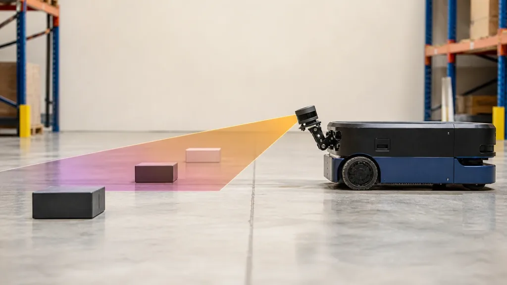
Consider a small indoor AMR that moves totes between storage lanes and a packing area. The program wants one compact depth sensor to help with aisle-edge awareness, rack-end obstacle checks, and approach confidence near a docking zone. The engineering question is not whether the sensor can produce depth data in principle. It is whether the robot can rely on that data in the exact geometry and lighting the warehouse will expose every day.
- Mount the module at the planned robot height and measure the useful view against the real aisle width, not a simplified hallway.
- Record repeated passes with empty aisles, parked pallets, tote overhangs, and partially protruding rack inventory.
- Repeat the run near open doors or bright spill zones if the warehouse has them.
- Review the saved frames to see whether rack-end corners and short obstacles remain visible when the robot approaches at realistic speed.
- Approve the module only if the team can show stable, replayable evidence that the chosen mount and data path support the target mapping behavior.
This kind of case keeps the evaluation honest. It forces the buyer and engineer to judge the module as part of a robot workflow instead of as an isolated box on a bench.
Common mistakes when screening a compact sensor for AMR mapping
- Buying on maximum range when the real challenge is short-range aisle coverage and rack-end visibility.
- Ignoring blind spots created by the robot bumper, mast, or payload fixture.
- Testing only in a clean corridor instead of a cluttered aisle with reflective wrap or irregular load edges.
- Choosing the final deployment interface too early instead of the fastest proof path for recorded data.
- Judging the sensor by a live visualization without saving evidence that can be replayed after a failure.
- Treating occupancy-grid output as a software problem only, when bad coverage or unstable returns are often the upstream cause.
RFQ and engineering approval checklist
| Checklist item | Why it belongs in the approval sheet |
|---|---|
| Exact robot task | Keeps the project tied to aisle mapping, obstacle checks, or docking support instead of a vague "robot vision" goal. |
| Mounting height and standoff | Prevents a promising FoV number from hiding a geometry mismatch. |
| Aisle width and critical obstacle sizes | Defines whether the sensor must resolve both rack edges, pallet corners, or low obstacles. |
| Preferred first interface | Reduces time to the first replayable dataset. |
| Host environment and logging plan | Ensures the evaluation fits the actual bench and robot stack. |
| Lighting and reflective-material conditions | Forces the pilot to include the real warehouse failure modes. |
| Acceptance evidence | Defines which runs, datasets, screenshots, and failure notes count as a pass. |
| Technical follow-up path | Lets the team move from evaluation to a focused vendor conversation using the product page and contact channel. |
When to move a compact depth module into the next AMR evaluation cycle
If your team already knows the aisle geometry, blind-spot zones, first data path, and approval evidence it expects, a compact dToF module can move from shortlist to a meaningful warehouse pilot quickly. If those answers are still vague, tighten the test sheet before you add autonomy work on top of weak sensor assumptions.
- Share the real aisle width, rack spacing, mounting envelope, and obstacle classes instead of asking for a generic robotics sample.
- State the preferred interface and replay workflow so the first bench run creates evidence, not just impressions.
Purpleriver, founded in 2015, develops solid-state dToF LiDAR technology and publishes documentation and sample resources that can support an evaluation workflow around the MRP-LD1 module.
Contact Purpleriver with your AMR aisle-mapping requirements so the next discussion starts from actual geometry, data flow, and approval criteria.