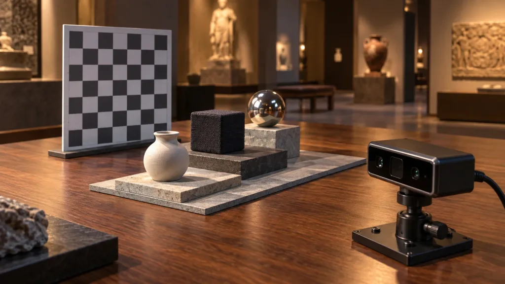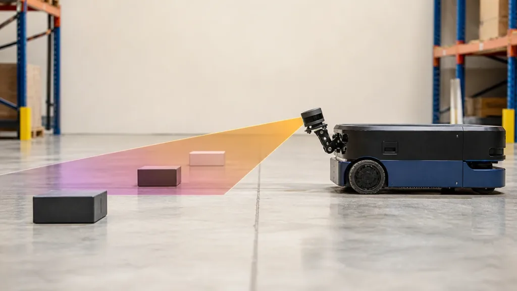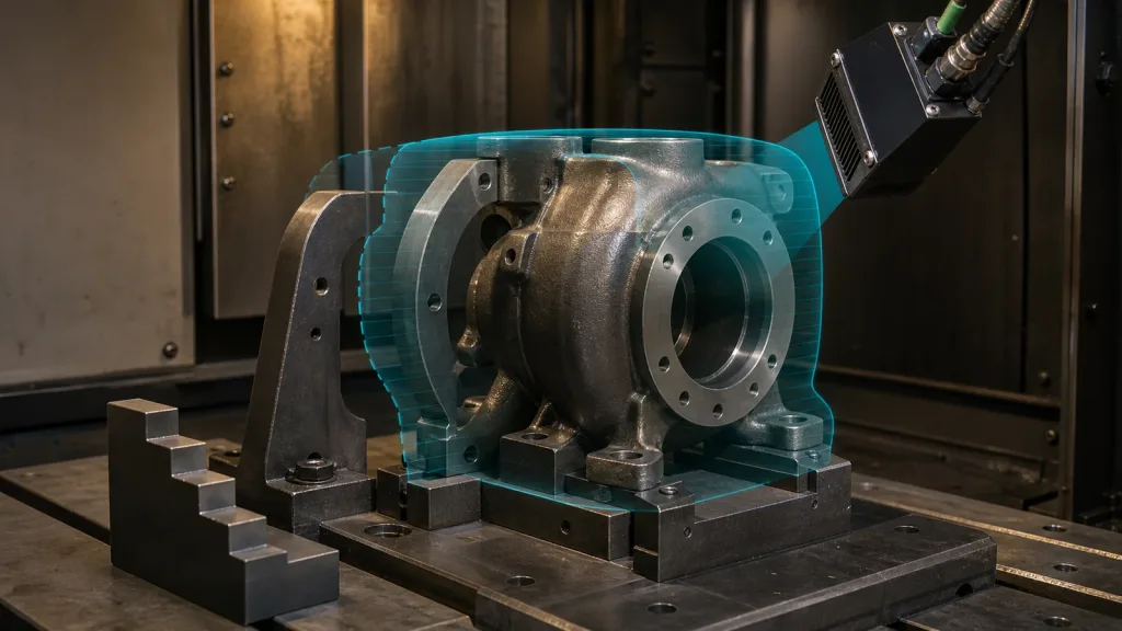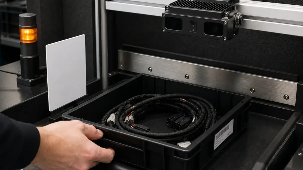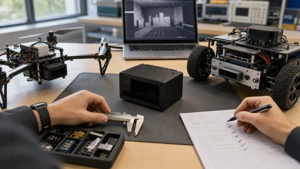
Solid-State LiDAR is easiest to overspend on when a team requests samples before it defines the mission, the usable range band, the logging path, and the pass/fail criteria for daylight testing. For compact UAV and robotics programs, the right question is not whether a module can produce 3D depth in a demo, but whether it can support a repeatable engineering decision with acceptable weight, power, field of view, data outputs, and outdoor behavior.
This guide is written for integration engineers and technical buyers who need a procurement scorecard before they commit bench time, airframe changes, or embedded-software effort to a new perception module.
| Quick answer | Choose a compact solid-state LiDAR module only after you convert its published specs into a scorecard covering detection volume, outdoor range, interface fit, replay workflow, and acceptance tests tied to your real program. |
|---|---|
| Best fit | Teams screening low-power 3D sensors for UAV obstacle awareness, altitude hold, terrain following, robot navigation, or early industrial-inspection prototypes. |
| Decision rule | If the team cannot define what counts as a failed daylight test, an unusable interface path, or an unacceptable blind zone, the module is not ready for procurement. |
Why compact teams buy solid-state LiDAR differently
Large mapping payloads and automotive-grade systems are not the right baseline for every program. Small UAV and robotics teams usually need a lighter, lower-power sensor that can deliver enough depth awareness for short-range perception without turning the integration plan into a new platform program. STMicroelectronics describes direct ToF sensors as compact, low-power solutions and frames robotics and drones around obstacle detection, cliff and collision avoidance, 3D mapping, and SLAM. That is useful context, but it does not tell a buyer whether one specific module is worth the next sample cycle.
Operational discipline matters too. The FAA Part 107 summary updated on July 6, 2026 says operators must keep the drone within sight and avoid careless or reckless operation. EASA’s open-category guidance likewise keeps visual line of sight central, with limited observer-based exceptions. In practice, a perception module can support safer workflows, but it should never be treated as a substitute for test planning, pilot responsibility, or fallback procedures.
If your team needs the broad baseline first, Purpleriver already covers solid-state LiDAR versus mechanical LiDAR for UAV platforms. This article starts later in the buying cycle: turning published module facts into a sample-request scorecard.
Solid-State LiDAR scorecard before sample request
| Scorecard area | What to verify | Why it matters | Reject if |
|---|---|---|---|
| Detection volume | FoV, minimum range, outdoor usable range, blind zones from housing or airframe geometry | The sensor only creates value if it covers the exact collision, landing, or navigation volume your program cares about | The useful cone misses the obstacles or ground geometry you must detect |
| Program fit | Weight, power draw, supply voltage, enclosure impact, mount stability | A technically good sensor still fails if it breaks payload or power budgets | The module forces a major mechanical or power redesign |
| Data usefulness | Depth grid, point cloud path, output cadence, logging and replay workflow | The team must be able to capture, inspect, and compare results quickly | No one can replay the data or derive a measurable acceptance check |
| Interface maturity | UART, UVC, UDP options; documentation; host compatibility | The fastest evaluation path is usually more important than the final deployment path | Bring-up depends on unsupported tooling or undocumented packet handling |
| Outdoor robustness | Ambient-light tolerance, reflective-surface behavior, dropout pattern, vibration sensitivity | Short-range perception usually fails first in bright scenes, clutter, or moving platforms | The team cannot define a believable daylight acceptance test |
Exact featured-product parameters to screen
The current WooCommerce Featured product available for this workflow is the LiDAR Drone Module – MRP-LD1 Solid-State dToF Sensor. Use the published facts below as screening inputs, then confirm them through your own bench and guarded field procedures.
| Parameter | Published value | Procurement implication |
|---|---|---|
| Weight | 8g | Helpful for compact payload budgets, but still validate mounting stiffness and cable routing. |
| Power / supply | 1.2W at 5V | Check whether the existing rail can stay stable through throttle or compute-load changes. |
| Ranging principle | dTOF with SPAD scanning | Plan for depth-oriented outputs and define how your team will interpret confidence and dropouts. |
| Emitter | 940nm VCSEL | Window material, glare, and environmental lighting should be part of the test sheet. |
| Laser safety | Class 1 (FDA Recognized Eye-Safe) | Useful for screening, but still document the operating context and integration procedures. |
| Range | Indoor 0.5-25m; outdoor 0.2-8m | For procurement decisions, base the scorecard on the outdoor band if the mission is daylight or mixed-light. |
| Ambient-light resistance | 80Klux | Midday and high-reflection tests belong in the acceptance plan, not as optional extras. |
| Accuracy | 0.2-1m <= +/-3cm; 1-5m <= +/-5cm; 5-8m <= +/-10cm; 8-15m <= +/-20cm | Translate each band into clearance margins, hover logic, or navigation thresholds. |
| FoV | 60° x 45° | Model whether one sensor covers both forward approach and near-ground geometry for your platform. |
| Resolution / rate | 40 x 30 at 10fps | Suitable for many short-range awareness tasks if the software stack can exploit a compact grid efficiently. |
| Interfaces | UART / UVC / UDP | Choose the path that reduces time to first replayable dataset. |
| Software support | Windows / ARM / Linux / Android | Useful when bench logging and deployment compute live in different environments. |
Selection workflow from shortlist to acceptance sheet
1. Define the Solid-State LiDAR mission before requesting hardware
Start with the task, not the datasheet headline. Is the program trying to add landing-zone awareness, near-field obstacle detection, corridor navigation, terrain following, or robot clearance checks? Write the range band, approach speed, mounting envelope, and manual fallback behavior first. A buyer who cannot describe those conditions is not ready to compare modules fairly.
2. Choose the fastest proof path, not the final architecture
The MRP-LD1 exposes UART, UVC, and UDP. For sample evaluation, the fastest path is usually the one that gets you replayable data with the least integration friction. Purpleriver’s documentation hub and sample datasets matter here because they reduce uncertainty before the team burns time on custom tooling.
3. Turn the datasheet into a measurable acceptance sheet
NIST’s 2025 publication on colored point-cloud evaluation is a useful reminder that sensor comparisons should rest on quantifiable measurements rather than on impressions from a single demo. For compact solid-state LiDAR screening, that means recording target-detection success, dropout frequency, frame-to-frame stability, and end-to-end latency against test scenes that reflect the real program.
4. Screen for integration risk before field scheduling
Weight and power are not enough. Confirm whether the mount angle creates blind zones, whether the 5V rail stays clean, whether the host platform can ingest the chosen interface, and whether the team can replay the data after a failed run. Purpleriver’s existing guide on how to choose a solid-state LiDAR module for drones is a useful baseline; this scorecard adds the pre-RFQ pass/fail logic that buyers usually miss.
5. Move into guarded outdoor or motion tests only after the bench sheet is stable
For UAV use, the FAA and EASA sources reinforce the same practical rule: evaluation discipline matters as much as sensor capability. The module should support safer testing, but the pilot still owns visual contact, procedural control, and contingency behavior. For robot pilots, apply the same mindset to aisle clutter, reflective targets, and stop conditions before the system is allowed near people or assets.
Interface, data, and integration planning
Most schedule slips happen after the team says “the module works” but before it proves “the module fits our stack.” Use the table below to align perception, embedded, and test owners early.
| Integration topic | Questions to answer before procurement |
|---|---|
| Mounting geometry | Will the sensor keep a stable view without prop guards, landing gear, brackets, or enclosures blocking the useful region? |
| Power path | Can the existing 5V rail absorb startup and operating load without noisy resets or corrupted data? |
| Output choice | Will the team process a compact depth grid, derive obstacle metrics, or replay point-cloud-like outputs for debugging? |
| Host environment | Will evaluation run on Windows, ARM, Linux, or a mixed workflow across bench and embedded targets? |
| Latency budget | How long from sensor update to warning, hover logic, slow-down command, or robot stop event? |
| Acceptance evidence | What exact logs, screenshots, and replay artifacts will convince the team that one module should move forward? |
If your roadmap leans toward flight awareness, review Purpleriver’s UAV navigation and obstacle-avoidance solution page. If the program leans toward floor robots and structured-environment sensing, the robotics 3D mapping page helps frame broader data expectations.
Realistic application case: one sample-evaluation plan for a drone team and a robot team
Consider an engineering group with two near-term pilots. One team wants short-range landing and obstacle awareness on a compact inspection UAV. Another wants corridor-clearance sensing for a small ground robot moving through reflective equipment aisles. Both groups are interested in the same class of compact solid-state LiDAR module, but neither wants to commit to a long integration cycle without evidence.
A practical shared evaluation plan is:
- Bench-test the module against representative targets at 1m, 3m, 5m, and the edge of the relevant outdoor band.
- Log data through the easiest interface first and verify the team can replay it without vendor-only tooling.
- Map the 60° x 45° FoV against each platform’s mounting angle to expose blind zones before fabrication changes begin.
- Run guarded tests around reflective surfaces, aisle clutter, or landing-zone contrast that match the real program.
- Approve the module for the next cycle only if both teams can document pass/fail evidence instead of “it looked good in the demo.”
This kind of shared scorecard keeps sample evaluation grounded in engineering evidence and prevents a compact module from becoming an open-ended research project.
Common mistakes when screening solid-state LiDAR modules
- Using the indoor headline range as the procurement basis for an outdoor daylight task.
- Choosing a module before checking whether one sensor placement covers the needed obstacle and ground geometry.
- Optimizing for the final interface architecture instead of the fastest replayable evaluation path.
- Ignoring how glare, reflective targets, vibration, or enclosure windows affect short-range performance.
- Accepting a demo without a written evidence package of logs, thresholds, and failure conditions.
- Treating the sensor as an autonomy substitute instead of part of a broader operational and software workflow.
RFQ and engineering evaluation checklist
| Checklist item | Why it belongs in the RFQ or sample request |
|---|---|
| Program type and sensing task | Keeps the vendor discussion tied to obstacle awareness, terrain following, navigation, or inspection rather than vague “3D sensing.” |
| Target range band and lighting conditions | Prevents the indoor headline spec from masking the real daylight requirement. |
| Payload, power, and enclosure limits | Filters out modules that look good on paper but do not fit the platform budget. |
| Preferred evaluation interface | Shortens time to first usable dataset and replay session. |
| Acceptance thresholds | Turns the first sample into a measurable scorecard rather than a one-off demo. |
| Host operating environment | Ensures tooling exists for Windows, ARM, Linux, or Android as needed. |
| Mounting geometry and blind-zone assumptions | Surfaces airframe or chassis issues before procurement progresses. |
| Vendor follow-up path | If the module passes, the team should already know how to continue through Purpleriver’s contact channel. |
When a compact solid-state LiDAR module is worth the next sample cycle
If your team already knows the sensing volume, the lighting conditions, the logging path, and the pass/fail evidence it needs, a compact module can move from shortlist to meaningful validation quickly. If those answers are still vague, tighten the scorecard before requesting hardware.
- Send the real range band and lighting condition, not only a general application label.
- Include the preferred interface and host environment so the sample arrives with a usable evaluation path.
Purpleriver’s featured MRP-LD1 solid-state dToF module is relevant for UAV obstacle awareness, altitude hold, terrain following, robot navigation, and industrial-inspection workflows. If the scorecard passes, move into the next vendor conversation with the exact range band, interface preference, and mounting constraints your team is screening against.
Contact Purpleriver with the completed scorecard so the discussion starts with usable engineering data instead of a generic sample inquiry.