
Sense
MRP-LD1 measures the configured sector and produces depth information from the observed scene.
Compact dToF sensing for UAV obstacle awareness, altitude support and controlled integration evaluation.
Explore the moduleUAV sensing solution
Evaluate MRP-LD1 as a compact UAV obstacle avoidance sensor for forward, downward or rear-sector depth input. The 8 g solid-state dToF module supplies depth data; host perception, decision logic and flight control complete the response.
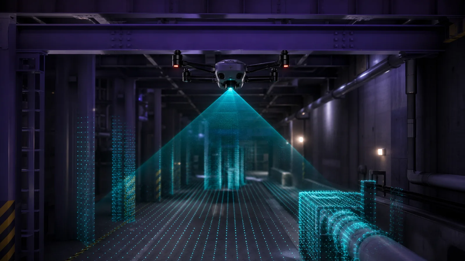
System architecture
An obstacle-avoidance function is an end-to-end timing and control problem. Keep the sensing module, data transport, host interpretation and motion authority separate so each layer can be measured and validated.
MRP-LD1 measures the configured sector and produces depth information from the observed scene.
UART, UVC or UDP carries the selected data path to the host processor or development platform.
Host-side software filters measurements, applies thresholds and combines the data with mission logic or other sensors.
The flight controller executes braking, diversion, hold or another response inside a validated operating envelope.
Coverage and mounting
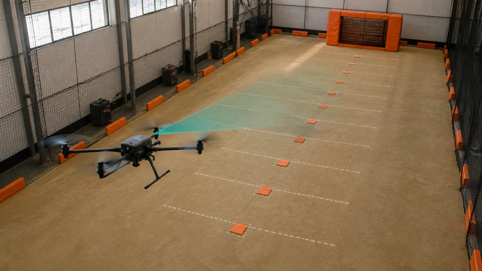
A single field of view cannot cover every approach direction. Start with the mission hazard, define the required sector, and then evaluate mounting position, overlap, airframe occlusion and remaining blind zones.
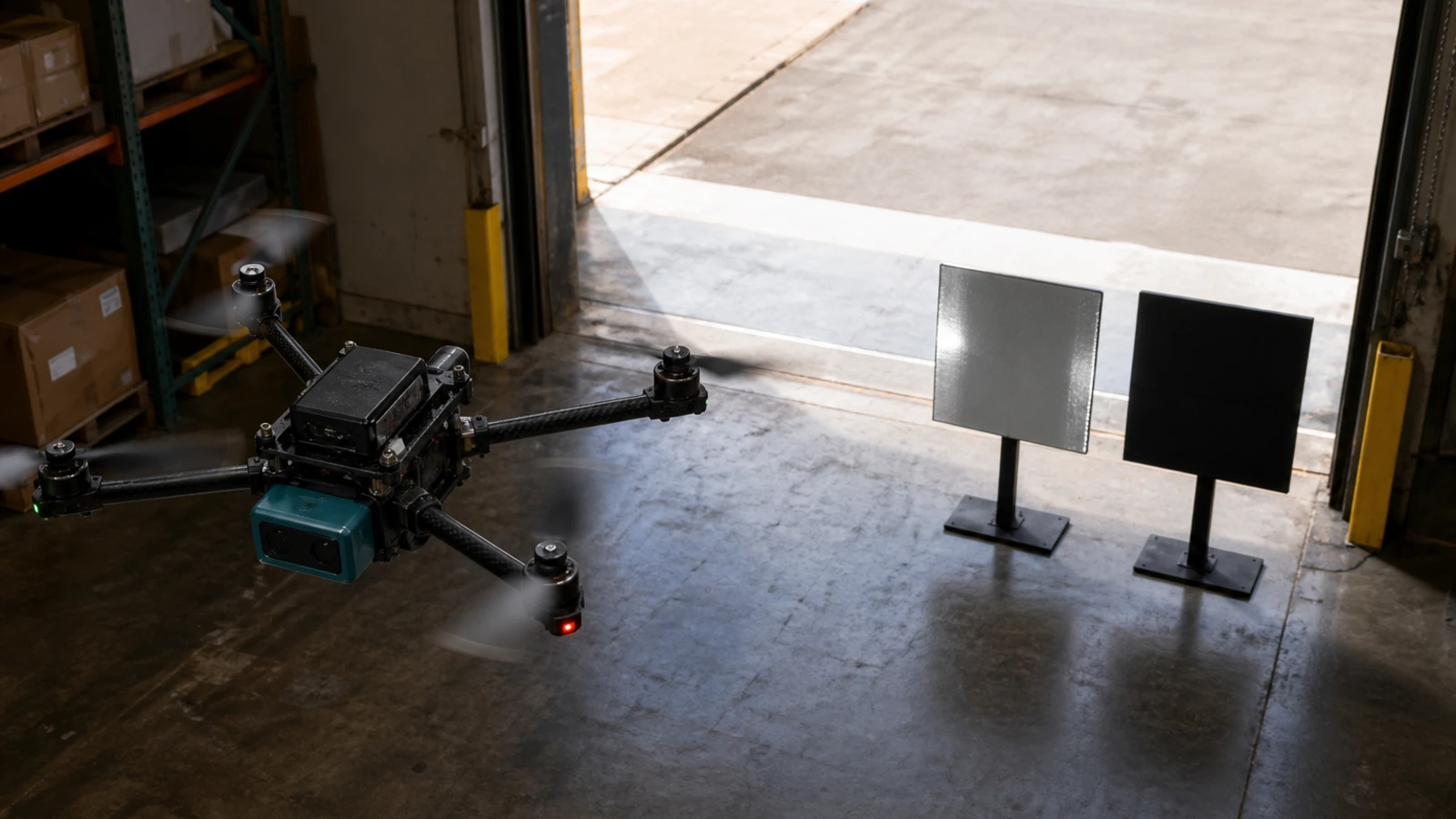
Connect target distance, sensor output, host latency and aircraft speed to a verified braking or diversion margin. Test small, dark and angled targets rather than relying on a single wall target.
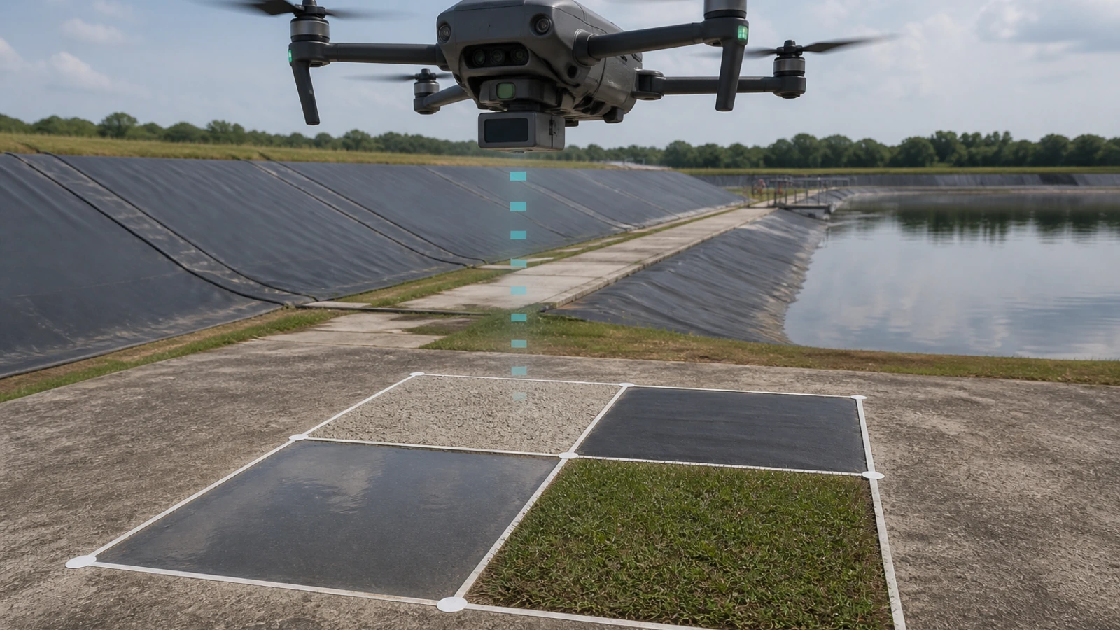
Evaluate altitude and landing-support concepts across concrete, vegetation, water-adjacent areas and surface transitions. Mounting angle and airframe occlusion must be checked on the actual UAV.
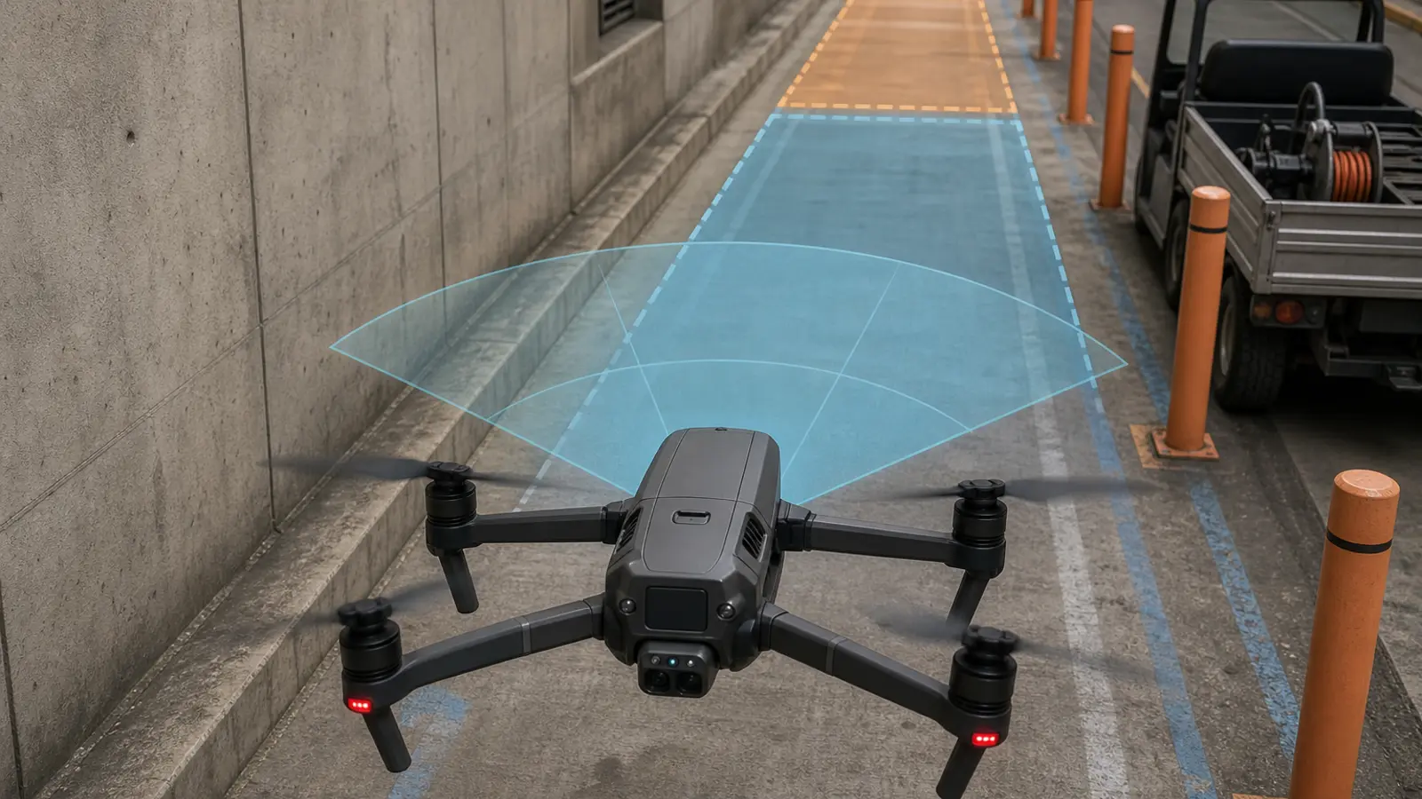
One 60° × 45° field of view is not omnidirectional coverage. Add rear or side sectors only where the mission requires them, then document overlaps and remaining blind zones.
MRP-LD1 module fit
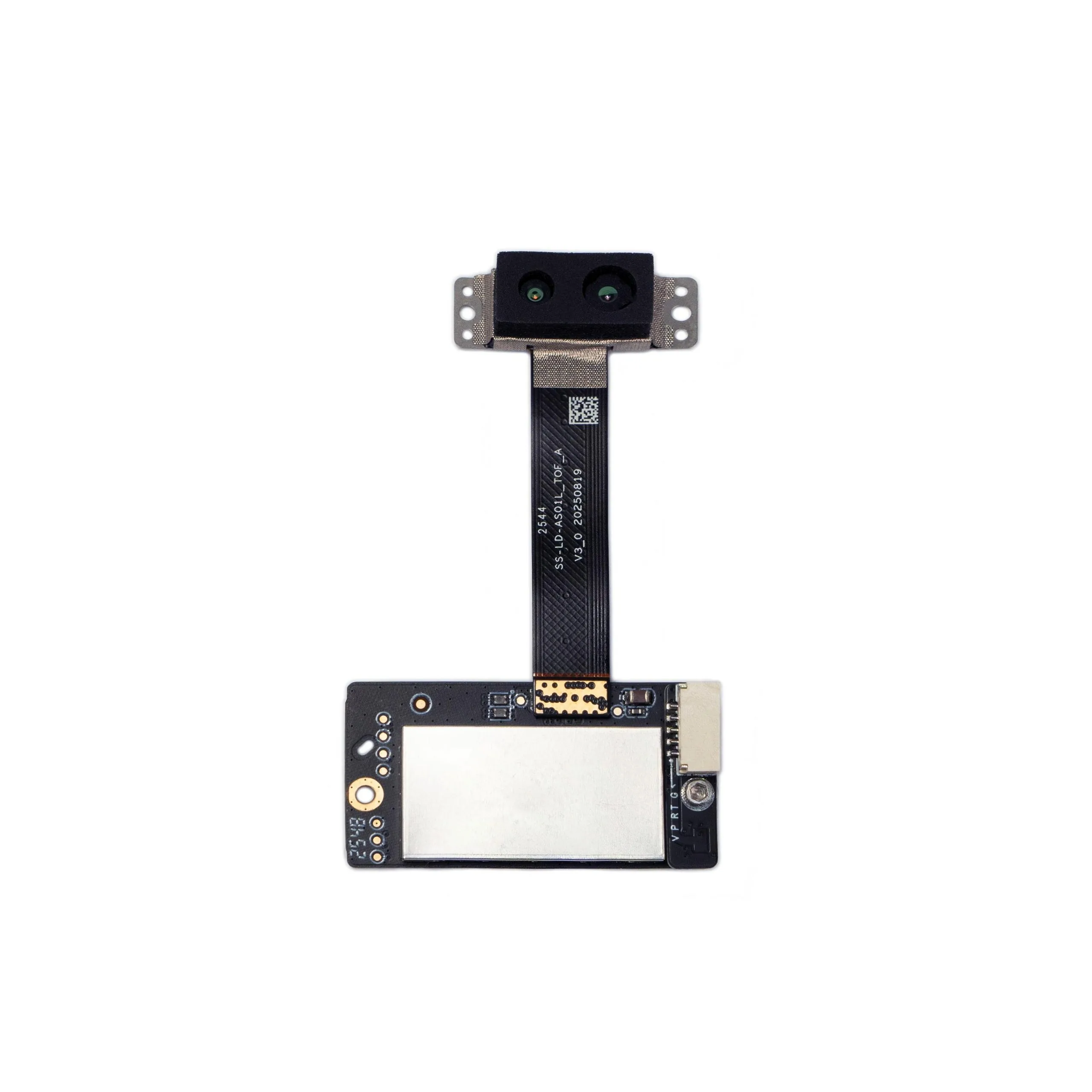
MRP-LD1 is a compact UAV obstacle avoidance dToF module based on SPAD direct time of flight and a 940 nm VCSEL. Treat each specification as an evaluation baseline and record the conditions that produce an acceptable or unacceptable result.
Documented baseline; validate target and sunlight.
Use the actual corridor, target and mounting position.
A defined sector rather than 360° coverage.
Include host and controller latency in the timing budget.
Review the complete mounted payload and cable path.
Validate the real power rail and transient behavior.
A starting reference, not a substitute for scene testing.
Choose the path that matches the host and software stack.
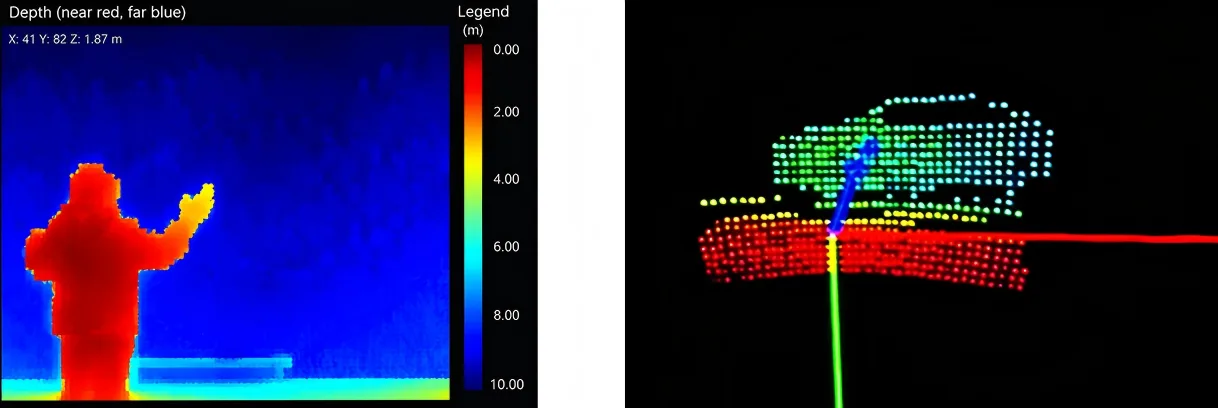
Depth-data handoff
The module provides measurement data, while the host decides how to filter, transform and apply it. Confirm coordinate conventions, timestamps, invalid values, thresholds, logging and failure handling before connecting the data to flight behavior.
Application paths
These are evaluation paths rather than autonomous-flight promises. Final fit depends on the target scene, host stack, vehicle dynamics and acceptance criteria.
Evaluate nearby geometry as one input to collision-risk logic in controlled flight conditions.
For a drone altitude hold LiDAR evaluation, use downward range input only after validating the target surfaces, mounting and landing-zone transitions.
Relate range data to terrain transitions, platform speed and host-control timing before expanding the route.
Assess proximity to structures where a compact sensing sector supports operator or autonomy safeguards.
Bench-to-flight validation
The documented 10 fps output is only one part of the timing budget. Measure transfer, host processing, decision and controller delay together, then set speed and response distance inside the demonstrated system margin.
Confirm 5 V power, selected interface, data units, timestamps and known-distance targets before platform motion.
Repeat tests with the real target size, material, angle, background, sunlight direction and working distance.
Measure airframe occlusion, vibration, alignment, enclosure effects and the complete processing delay.
Start inside a conservative speed and distance envelope with a manual fallback and recorded sensor data.
Save difficult frames, document missed or unstable detections and require evidence before widening the operating envelope.
Engineering resources
Use the product page for approved specifications, documentation for the integration path, and sample data for scene-level review. Keep the same application assumptions across each request.
Review the complete approved MRP-LD1 specification and application details.
View product details › 02Request the user manual, SDK package and UART/UVC/UDP integration material.
Open documentation › 03Describe the target scene and request sample data for technical evaluation.
Request sample data › 04Review the broader buying and application path for teams selecting a drone sensing module.
Open solution overview ›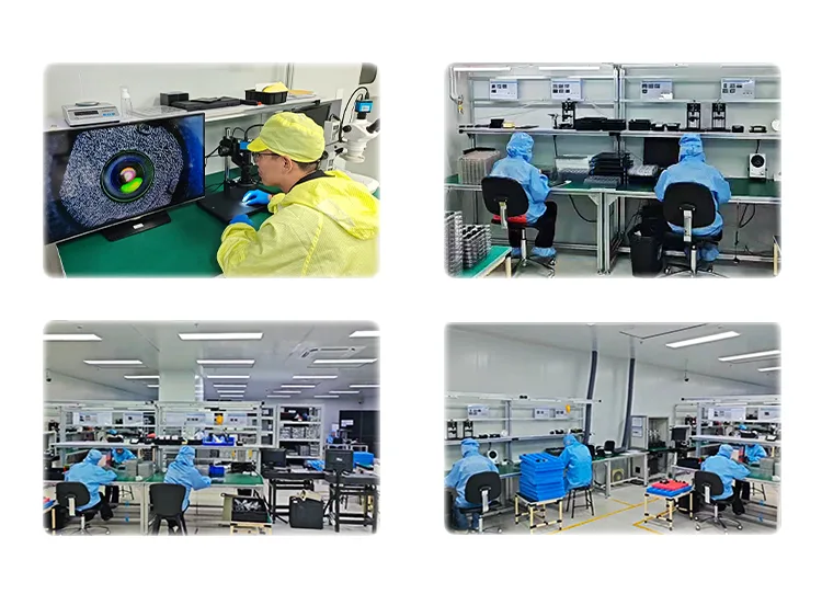
Engineering and supplier review
Founded in 2015, Guangzhou Purpleriver Electronic Technology Co., Ltd. develops thermal-imaging and solid-state dToF LiDAR technologies. UAV teams can move from public specifications to documentation, sample data, interface review and project-specific communication.
UAV integration FAQ
Confirm the sensing boundary, mounting plan, data path and validation conditions before sample evaluation.
Read the complete dToF LiDAR FAQNo. MRP-LD1 supplies depth information. The host processor, perception and planning software, flight controller and validated control response remain part of the complete system.
No. The documented field of view is 60° horizontal by 45° vertical. Forward, downward, rear or side coverage requires deliberate placement, overlap planning and blind-zone testing.
Use the documented 0.2–8 m outdoor range as a baseline. Actual usable range depends on target reflectivity, size, angle, sunlight, mounting, motion and the application acceptance criteria.
Relate the sensor frame interval to host transfer, filtering, perception, planning and controller delay. The safe speed and response distance must come from the measured end-to-end system, not the frame rate alone.
Use the documented 80 Klux ambient-light resistance as a starting reference, then test direct sunlight direction, dark and reflective materials, target angle, background and enclosure effects in the real scene.
MRP-LD1 lists UART, UVC and UDP. The choice depends on the host, required data path, software environment, bandwidth, logging and failure-handling design.
The approved application scope includes UAV altitude hold and terrain-following concepts. Final suitability depends on surface conditions, range, mounting, motion, host processing and system-level validation.
Share the UAV type, sensing direction, target size and material, working distance, lighting, speed, host platform, interface, payload and power limits, sample quantity and project schedule.
Project-specific review
Send the sensing direction, target, range, lighting, speed, host, interface, payload limit and schedule. Purpleriver can align the product, technical resources and next evaluation step with those requirements.
Drone LiDAR Quote
Share quantity, platform and integration needs. Justin Lu can follow up with quote, sample or technical support details.
Resource unlocked
Your inquiry has been submitted. You can download the requested resource now.
Download resource