
Obstacle awareness
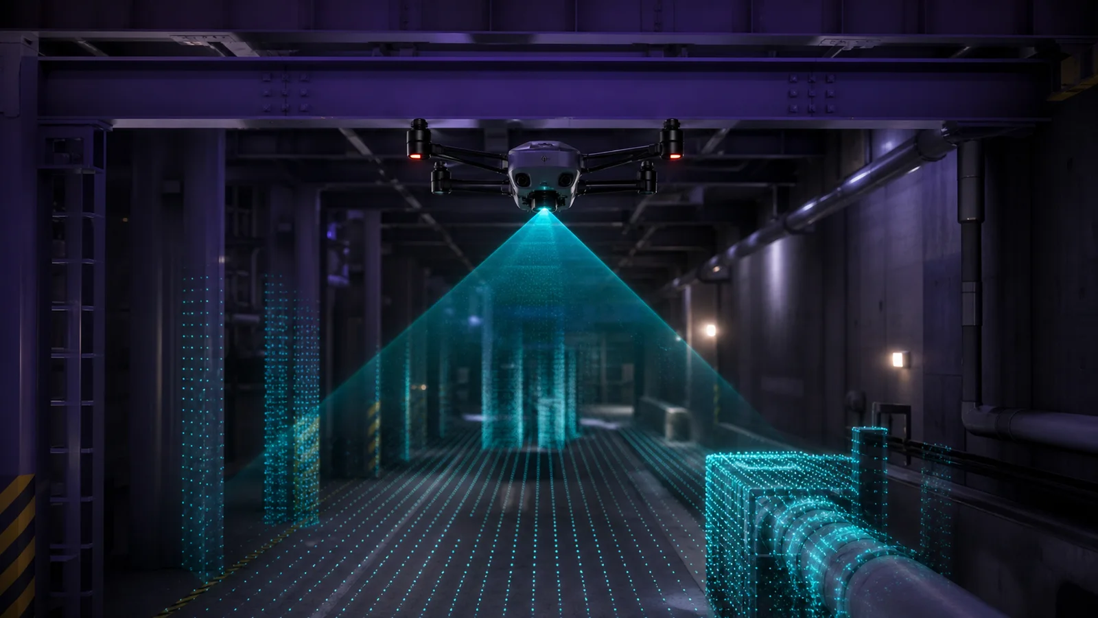
Capture object distance and scene geometry so the host system can evaluate collision risk and choose a response.
Review the path ›Drone LiDAR sitemap pages are being expanded with product-led technical content.
Explore the moduleApplication & Integration Hub
Drone LiDAR Solutions should start with the sensing task—not a generic technology list. Use this hub to match MRP-LD1 depth output to UAV obstacle awareness, robotics mapping, industrial inspection or embedded perception, then plan the host, interface and validation work around verified product data.
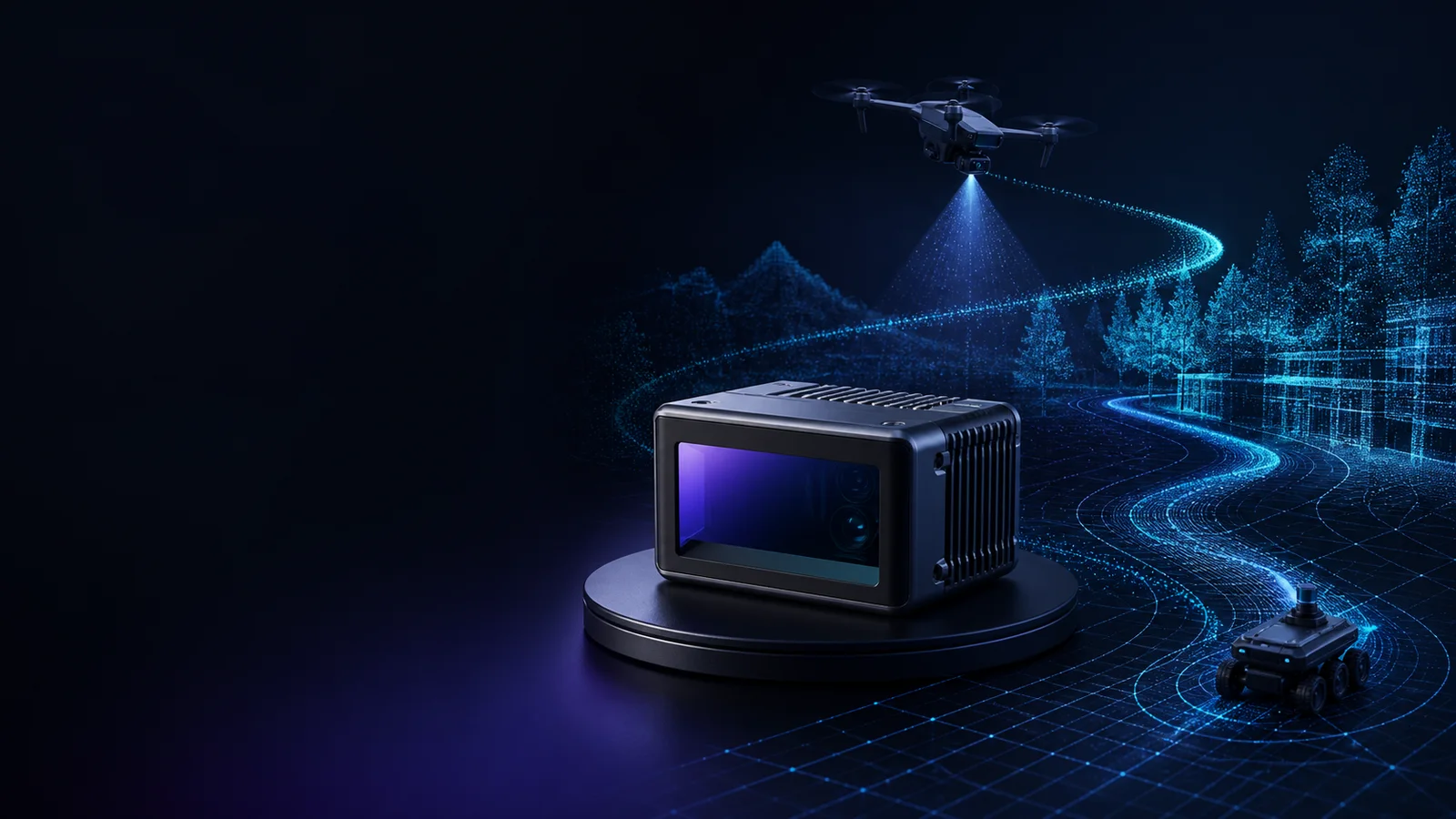
Start with the perception task
A solution page should answer what the sensor must observe, what data the host receives and what the wider system must still decide. These five tasks define the most practical starting points for MRP-LD1 evaluation.
Capture object distance and scene geometry so the host system can evaluate collision risk and choose a response.
Review the path ›Provide ranging input for altitude-hold and terrain-following concepts within the outdoor test envelope.
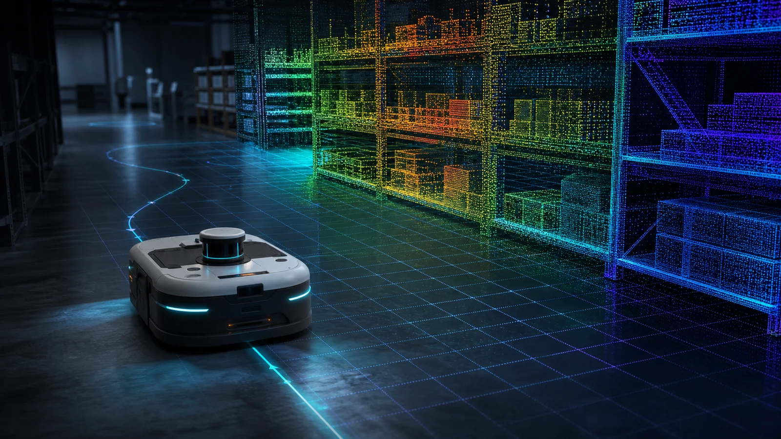
Review the path ›Deliver depth and point-cloud information for robot perception, route awareness and mapping development.
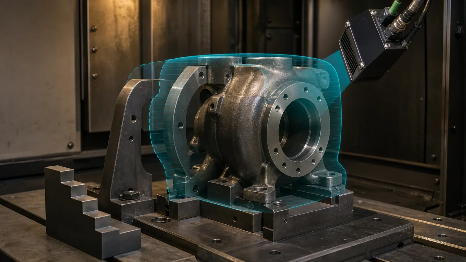
Review the path ›Measure controlled targets where stand-off distance, object profile or presence information supports inspection logic.
Review the path ›Evaluate 3D scene changes for security, smart equipment and host-controlled embedded perception workflows.
Review the path ›Application paths
Compare UAV LiDAR applications, robotics LiDAR solutions and industrial depth sensing workflows. The same dToF module can support each path, but the mounting, target set, timing budget and host-side software must be planned for the actual platform.
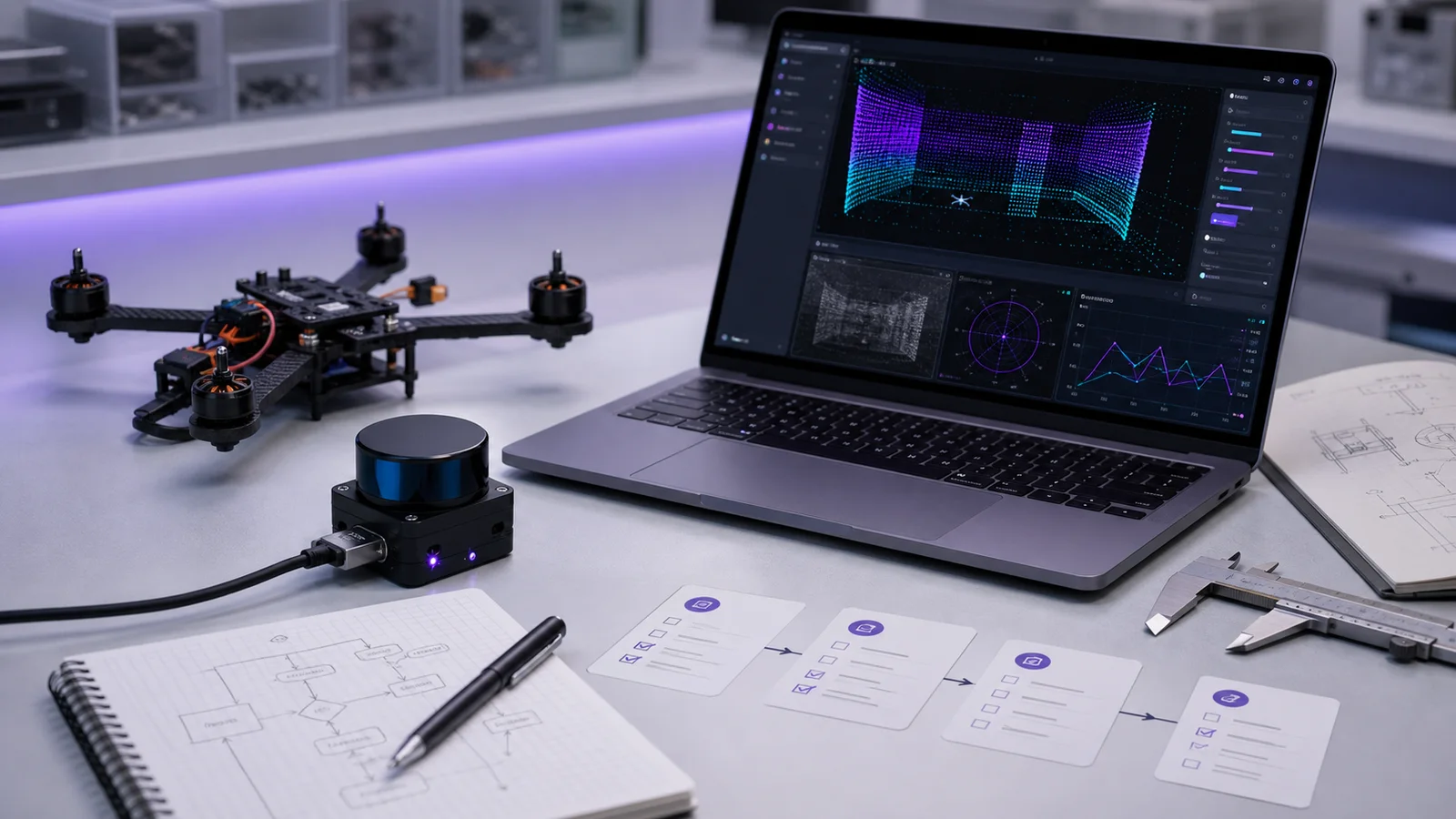
Sense, process and act
MRP-LD1 measures depth; it does not independently navigate a drone, steer a robot or stop a machine. A dependable solution assigns each responsibility to the correct layer and validates the handoff between them.
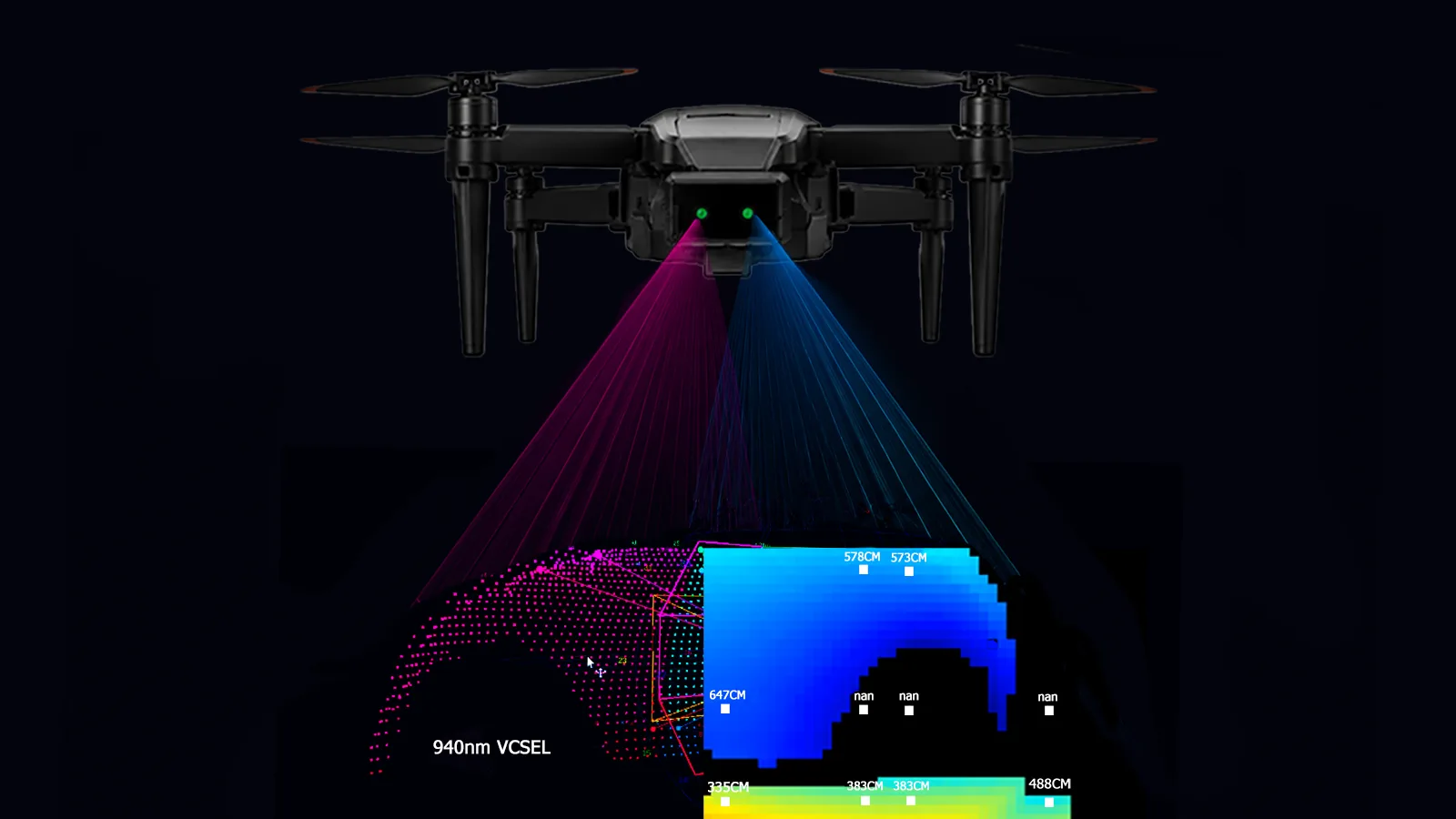
MRP-LD1 emits 940 nm light and measures direct time of flight to produce depth information.
UART, UVC or UDP carries the selected data stream to the PC, embedded host or development platform.
Host-side software filters data, applies thresholds and combines it with application logic or other sensors.
The flight controller, robot controller or machine logic decides and executes the system response.
MRP-LD1 platform
MRP-LD1 is a compact solid-state dToF sensing module for UAV, robotics and embedded 3D perception evaluation. It is not a complete drone, navigation stack, flight controller or autonomous decision system.
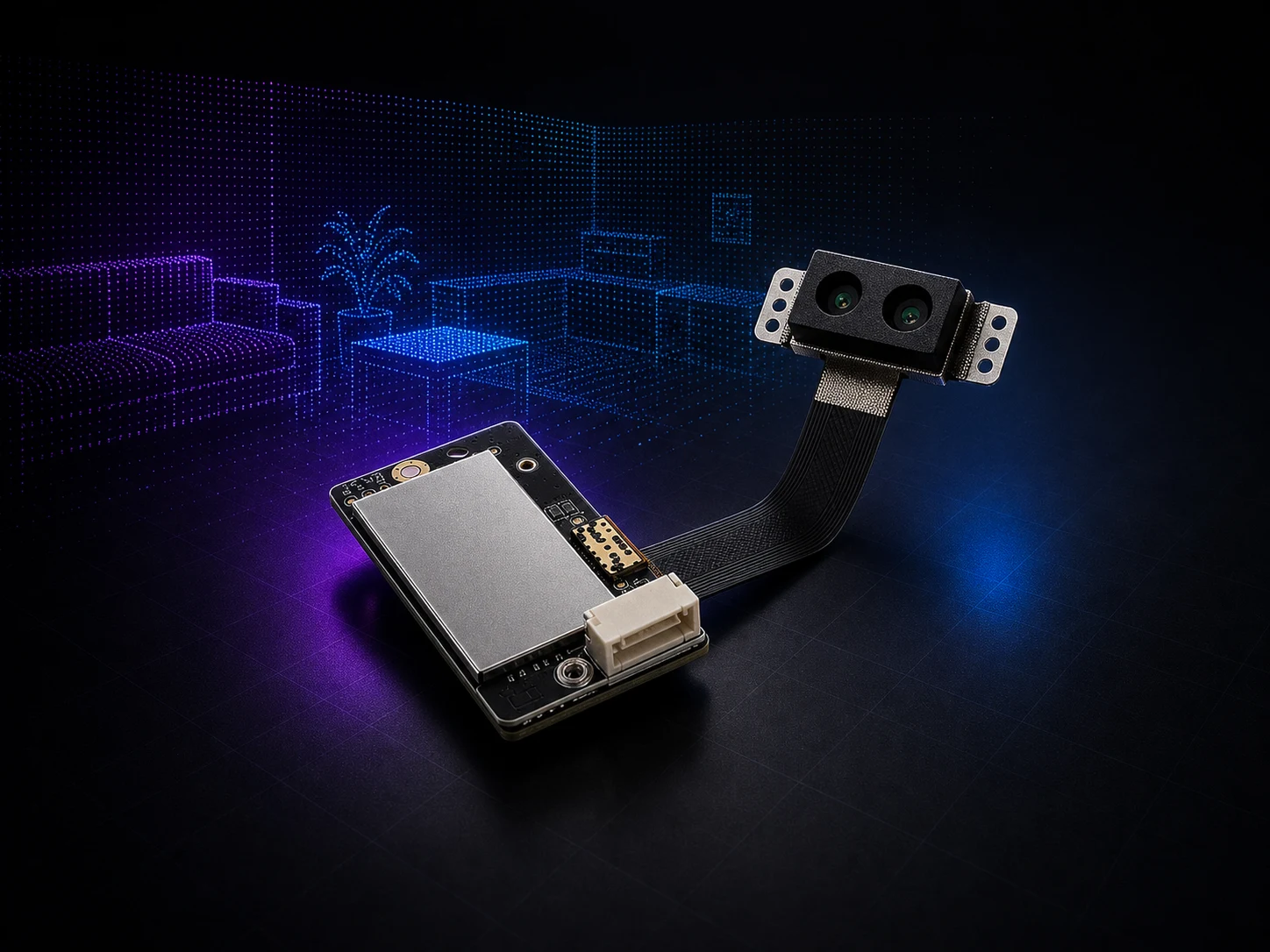
0.5–25 m indoor and 0.2–8 m outdoor listed ranging baselines; test target reflectivity and scene conditions.
60° horizontal × 45° vertical field of view for a defined sensing sector, not full 360-degree coverage.
40 × 30 depth output at 10 fps for early perception, thresholding and point-cloud evaluation.
8 g module weight, 1.2 W typical power and UART/UVC/UDP interfaces for compact host platforms.
Application validation
Catalog specifications are the baseline, not the acceptance test. A useful evaluation reproduces the target material, distance, lighting, speed, mounting and host-processing conditions that define success or failure.
Define the smallest relevant target, approach angle, background and required sensing sector.
Test dark, bright, small and angled targets across the actual working-distance window.
Use the listed 80 Klux resistance and outdoor range only as baselines; validate direct sunlight and glare in the target scene.
Relate 10 fps sensor output to platform speed, host latency, decision time and braking or maneuver margin.
Check enclosure edges, landing gear, vibration, contamination and multi-direction coverage gaps.
Confirm interface bandwidth, SDK environment, coordinate handling, logging and failure-state behavior.
Evaluation workflow
This five-stage path keeps the technical review, sample request and purchasing conversation tied to the same measurable requirements.
Record the platform, scene, target size, range, light level, speed, interface and acceptance criteria.
Compare verified specifications with payload, power, field-of-view and host-processing limits.
Review the user manual, SDK path and representative depth or point-cloud output before integration.
Validate static targets first, then repeat with realistic motion, lighting, mounting and controlled failure cases.
Share test findings, configuration needs, sample quantity and project timing before pilot or volume planning.
Purpleriver evaluation support
Technical selection is easier when the product specification, host interface, sample data and commercial request describe the same application. Purpleriver supports that handoff with documented resources and project-specific communication.
Use the manual, specification preview and interface notes to define electrical, mechanical and software work.
Plan evaluation around Windows, ARM, Linux or Android support documented for the module.
Request depth or point-cloud material that is closer to the target scene instead of relying on generic visuals.
Share the application, host, interface, quantity and timing so technical and purchasing questions stay aligned.
Solution FAQ
Use these answers to define the system boundary and prepare a more useful technical inquiry.
View the complete dToF LiDAR FAQNo. MRP-LD1 supplies depth information. The host processor, perception logic, decision layer and flight or robot controller remain responsible for interpreting the data and commanding the response.
The documented baselines are 0.5–25 m indoors and 0.2–8 m outdoors. Actual usable range depends on target reflectivity, size, angle, ambient light, mounting and motion, so the target scene must be tested.
No. The listed field of view is 60° horizontal by 45° vertical. Forward, downward, rear or multi-direction sensing requires deliberate module placement and blind-zone validation.
The module provides depth images and 3D point-cloud data. Documented interfaces are UART, UVC and UDP, with software support listed for Windows, ARM, Linux and Android.
Use the 80 Klux ambient-light resistance and 0.2–8 m outdoor range as starting references, then test actual sunlight direction, target material, background, enclosure and platform motion.
Include the platform type, sensing task, target size and material, working distance, lighting, speed, mounting direction, host platform, preferred interface, expected quantity and project timing.
Technical resources
Project-specific review
Share the platform, target, range, lighting, motion, host and interface. We will use those details to align the product, documentation, sample data and next technical discussion.
Drone LiDAR Quote
Share quantity, platform and integration needs. Justin Lu can follow up with quote, sample or technical support details.
Resource unlocked
Your inquiry has been submitted. You can download the requested resource now.
Download resource